
Overview
The Replace Switches tool in Advanced Matrix Programmer (AMP) is used to replace a switch in an existing system configured using Standardized Configuration.
This tool is intended for established systems only and is designed to quickly bring a replacement switch online with minimal disruption. It does not perform system configuration, device setup, or firmware validation.
At the end of the process, AMP performs a validation check to confirm the replacement switch was successfully applied and that all connected devices are patched correctly.
When to Use This Tool
- Replacing a failed switch in an existing Standardized Configuration system
- Swapping hardware with an identical or compatible supported switch
- Restoring system functionality without reconfiguring the entire deployment
Requirements
- The Just Add Power project report file or a completed takeover form.
- Optional: The Just Add Power project export file.
- A compatible switch listed under our Standardized Configuration Supported Switch List.
- A native Windows 10/11 PC with the latest version of Advanced Matrix Programmer installed
- An Ethernet connection on the same network as the control system and the AV over IP system.
Instructions
Note: For these instructions, we will be replacing the second switch of a three switch standardized system. You will change your steps according to the system you are servicing.
Part A: Getting Started
-
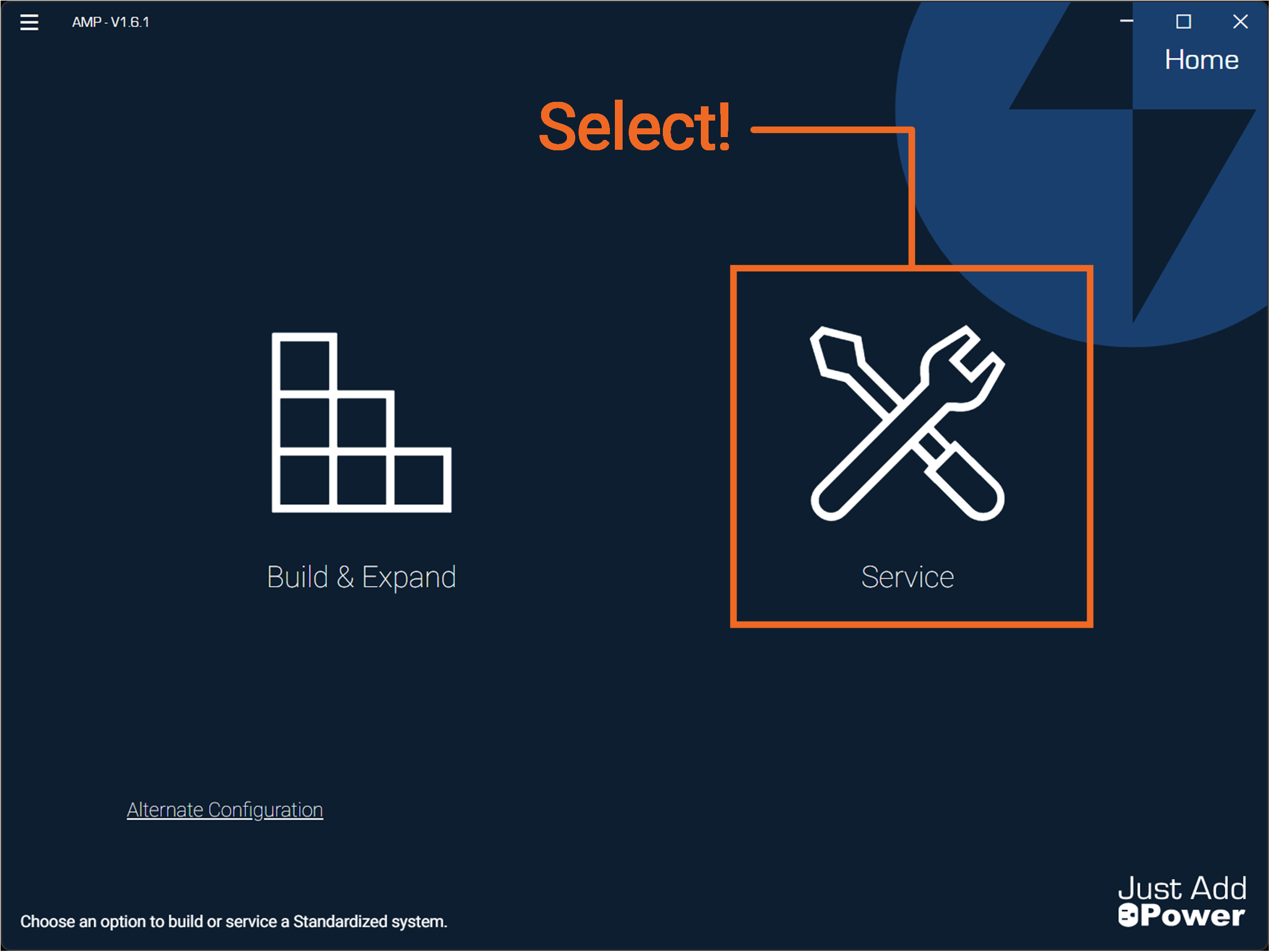
Open Advanced Matrix Programmer and select Service.
-
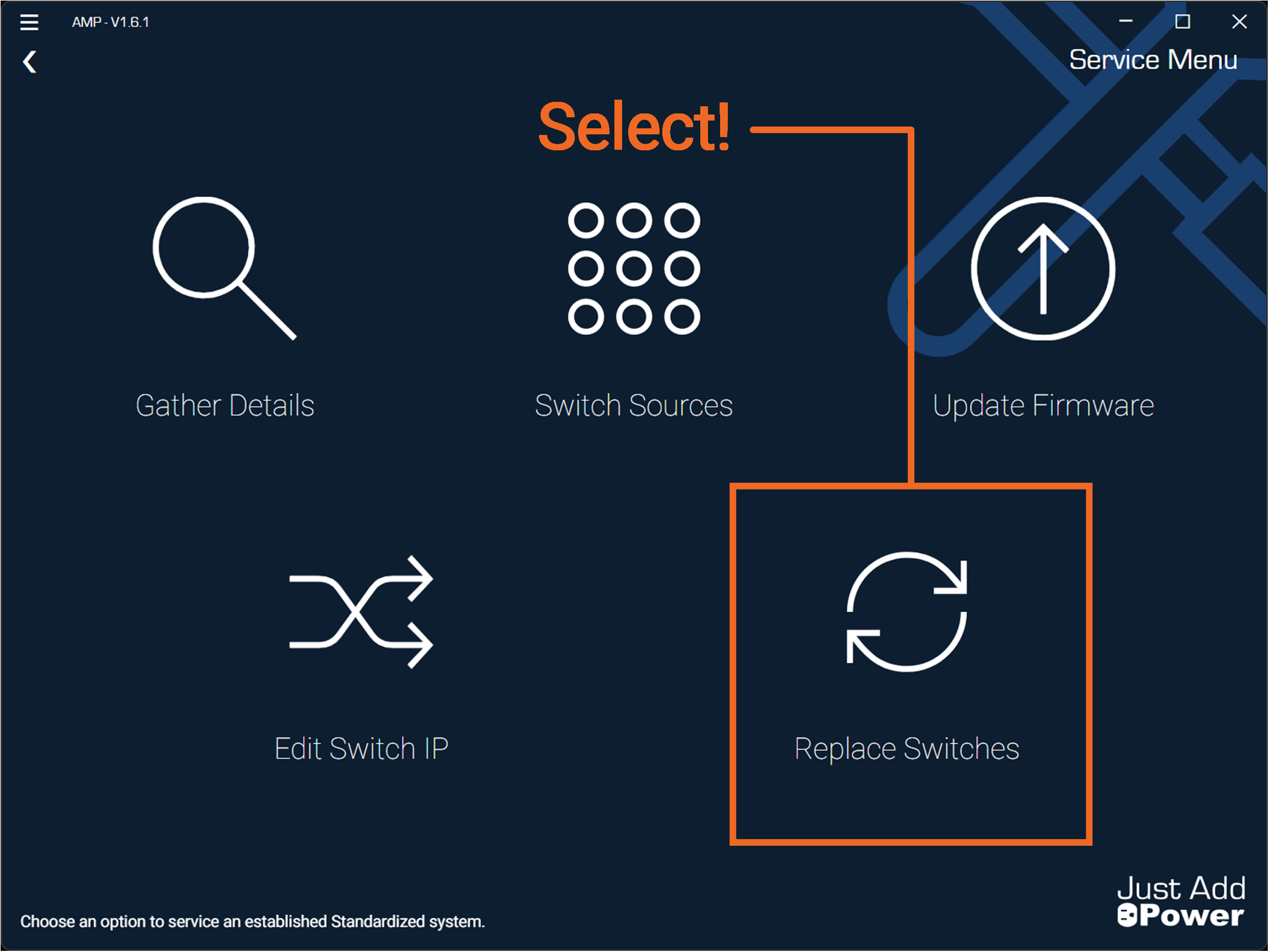
Select Replace Switches.
-
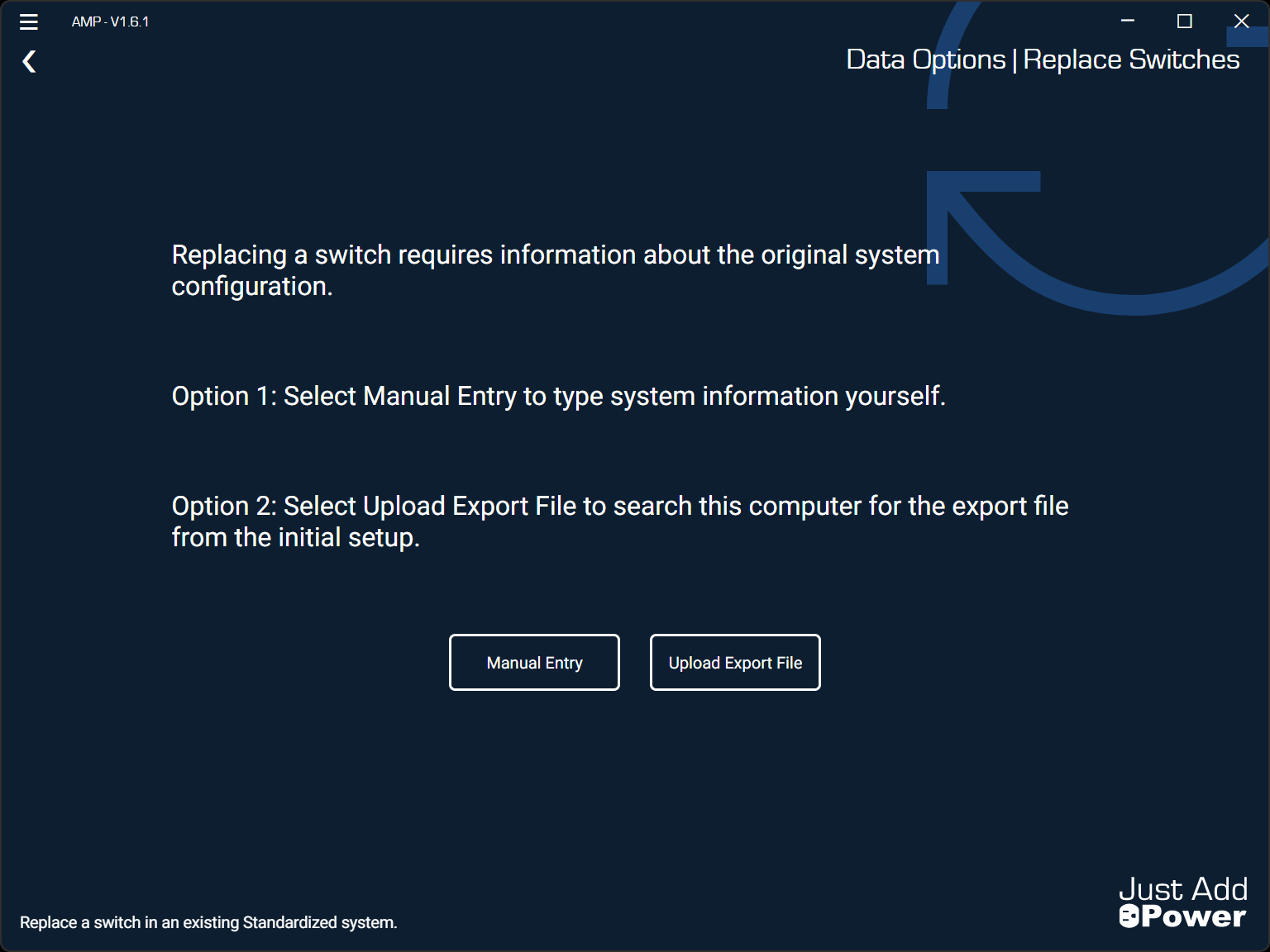
Choose Option 1 or Option 2 and gather the required files or documentation for your Project. If you are using the SAME PC that was used to set up the system originally, the files you need should be in AMP's Project Folder.
Part B: Enter Switch Details
Option 1 - Manual Entry
Manual Entry requires you to provide the exact details of the existing system:
- Number of Switches
- Switch Models
- Switch IP Address
- Switch Netmask
- Switch Gateway (Router IP)
- Decoder Count
- Encoder Count
This information can be found from the projects original report file or discovered by using and filling out a Takeover Form
For Just Add Power systems with multiple switches, you must provide the full system details for this tool to function correctly.
-
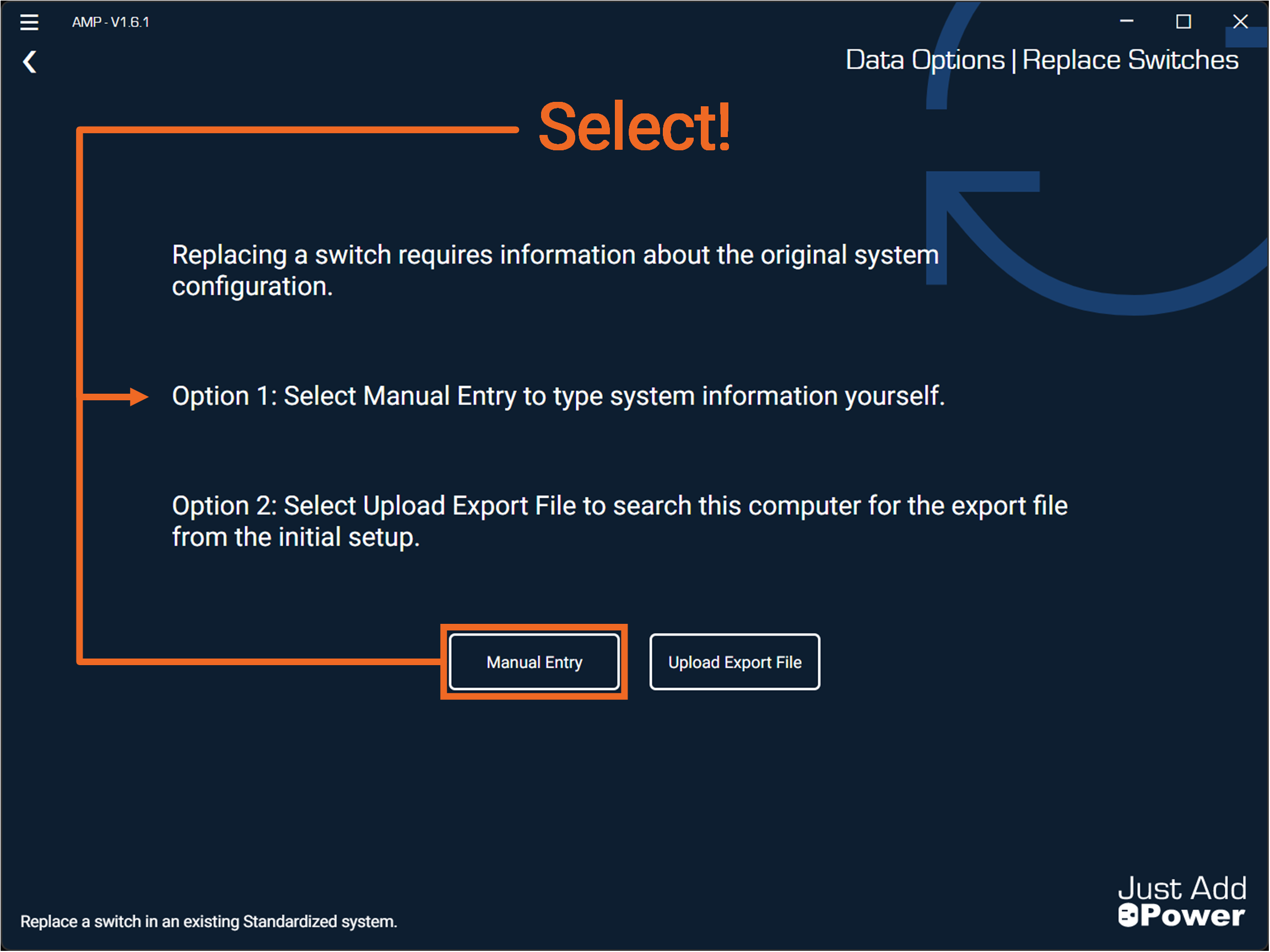
Select Option 1: Manual Entry.
-
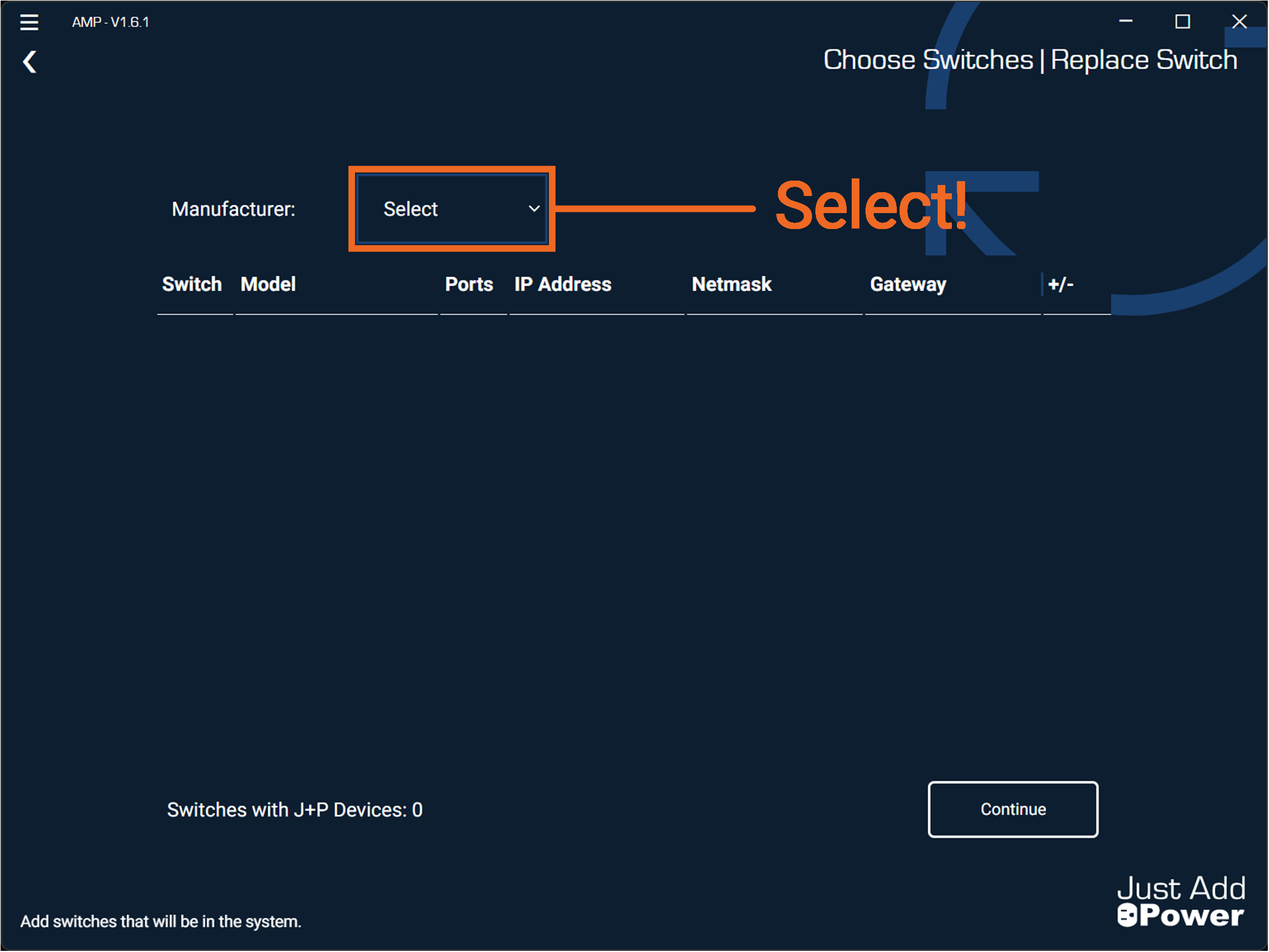
Select the switch Manufacturer for your established system.
-
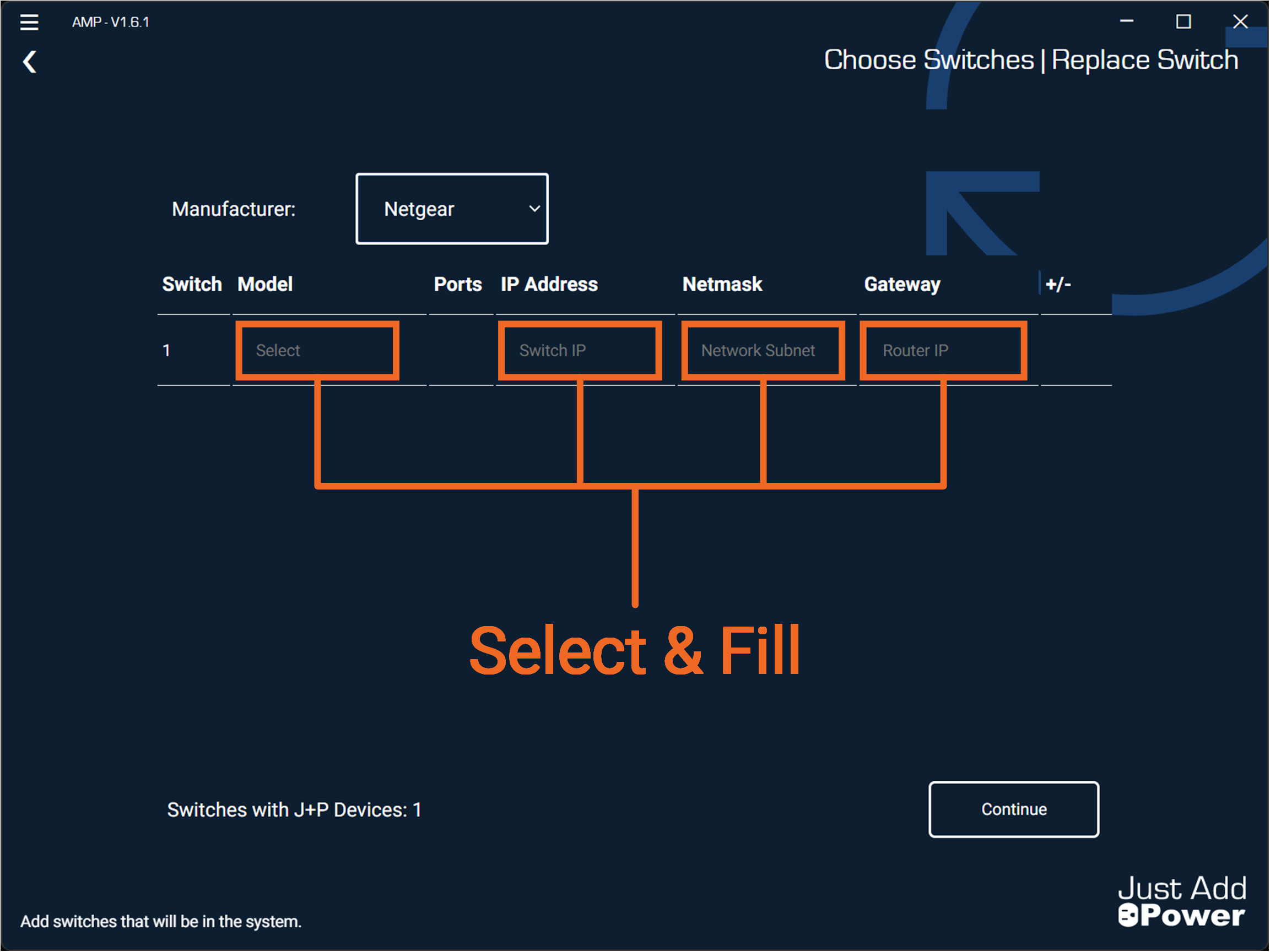
Select & fill the Model, IP Address, Netmask, and Gateway of the first switch.
For single switch systems, select "Continue" and skip to Step 5.
-
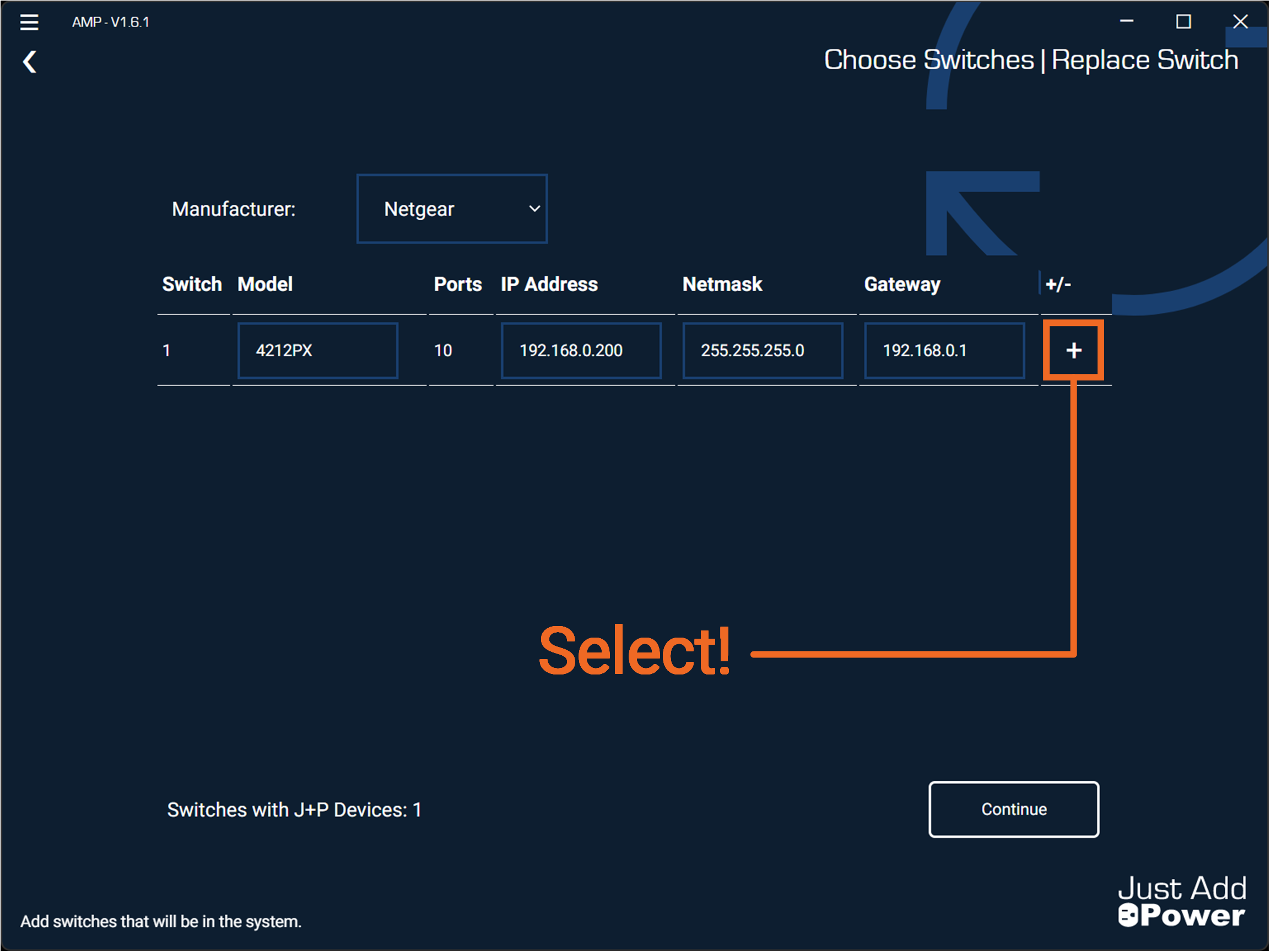
Select the "+" button to add additional switches. For these instructions, we will add two more switches for a total of three.
-
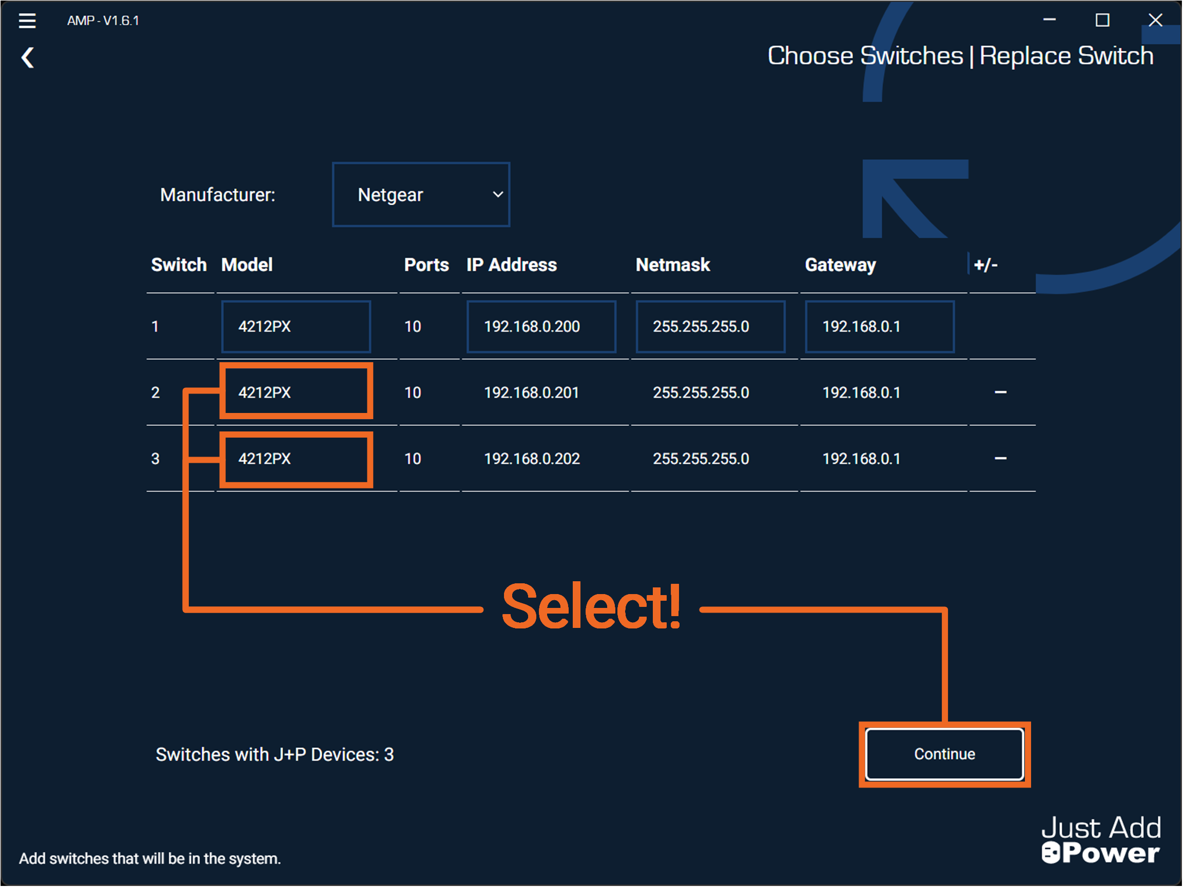
Select the models for the additional switches. Select "Continue"
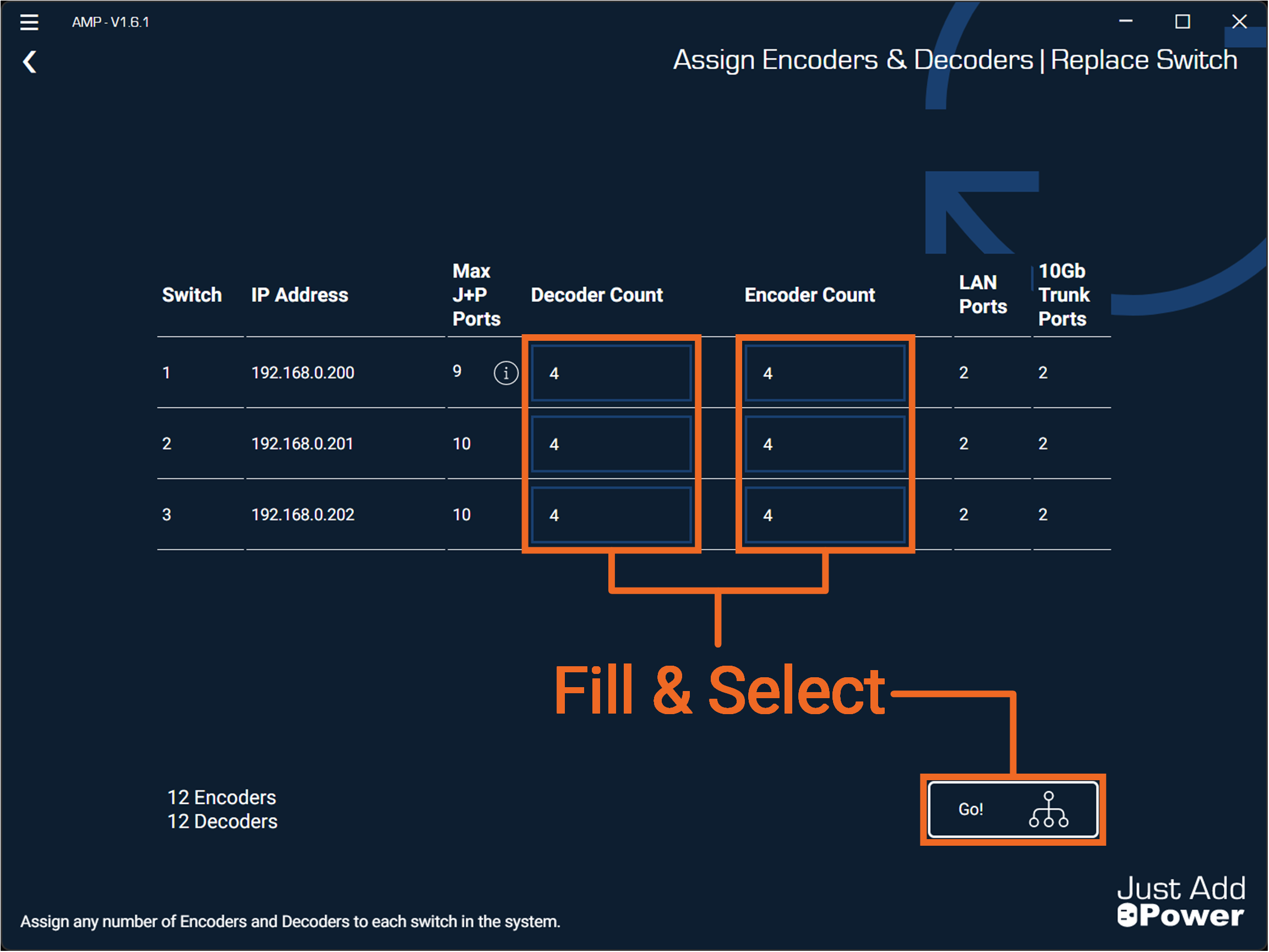
-
Fill the Encoder and Decoder counts for each switch in the system. Select "Go!"
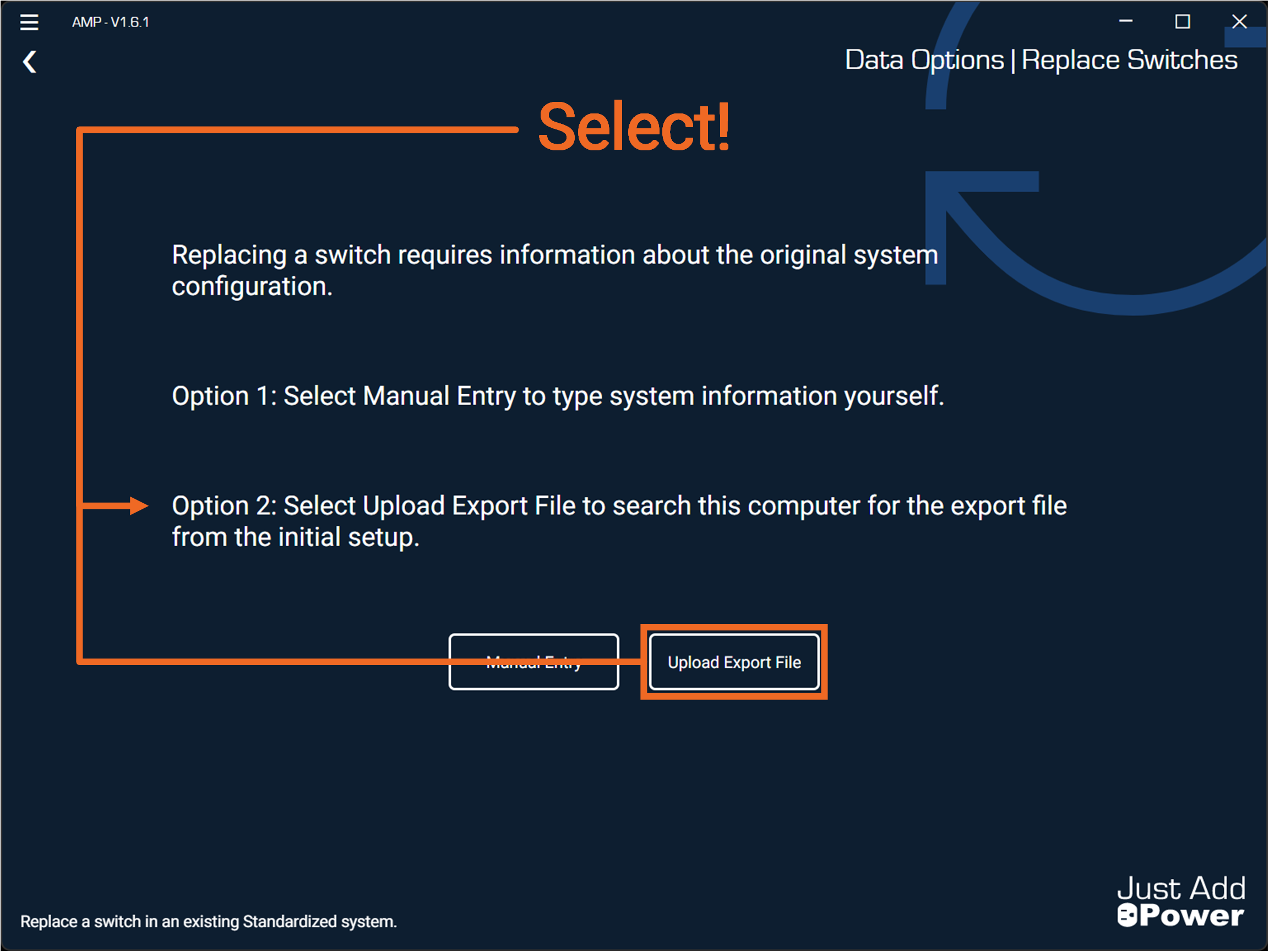
Option 2 - Upload Export File
Uploading an Export File automates the user entry portion of the Replace Switches tool.
This file is only available on the PC originally used to configure the system in AMP. It is located in the Projects Folder.
Option 2 does not function when using an AMP Report file or Switch Configuration.
-
Select Option 2: Upload Export File.
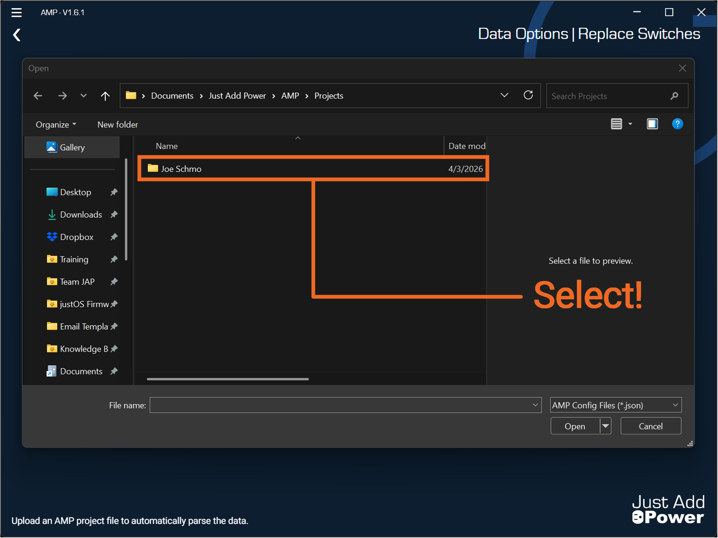
-
A Windows File Explorer will direct you to the local Project Folder. Select the project folder for the system. Project Folders are only generated when the PC was used to configure the system originally.
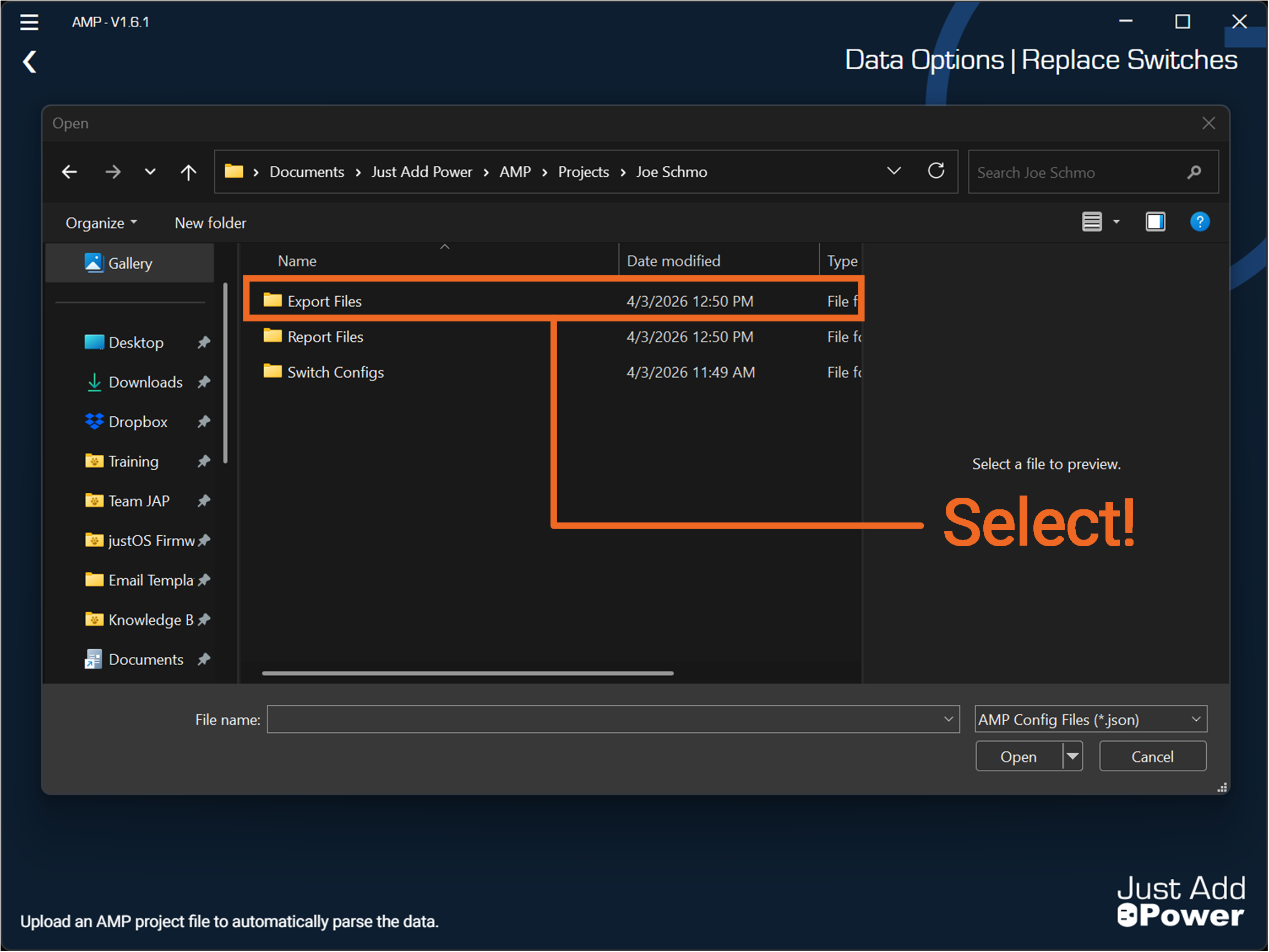
-
Select the folder named "Export Files"
-
Contained should be a file named,
"[$ProjectName]-export.json". Select the file and press "Open".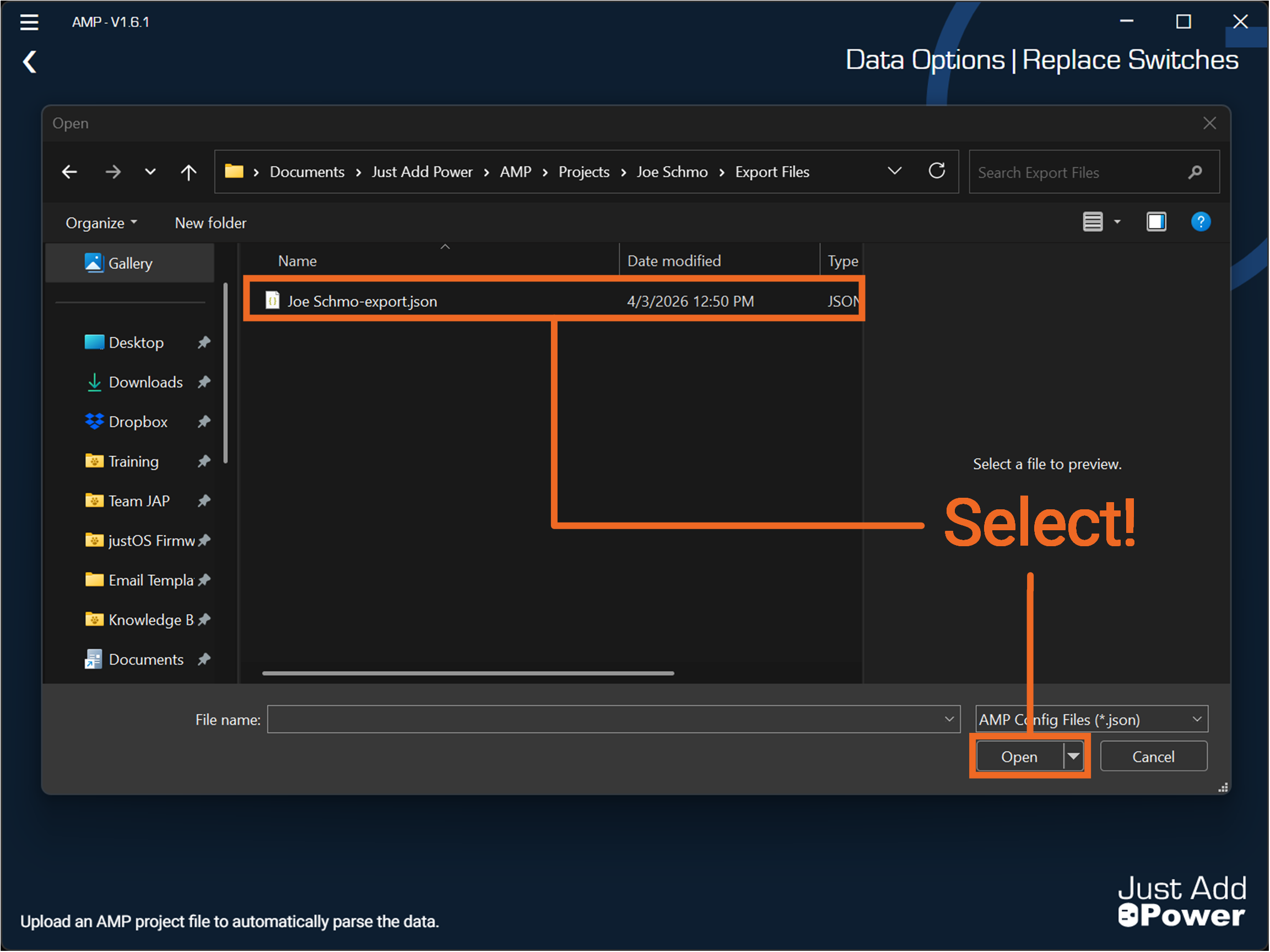
-
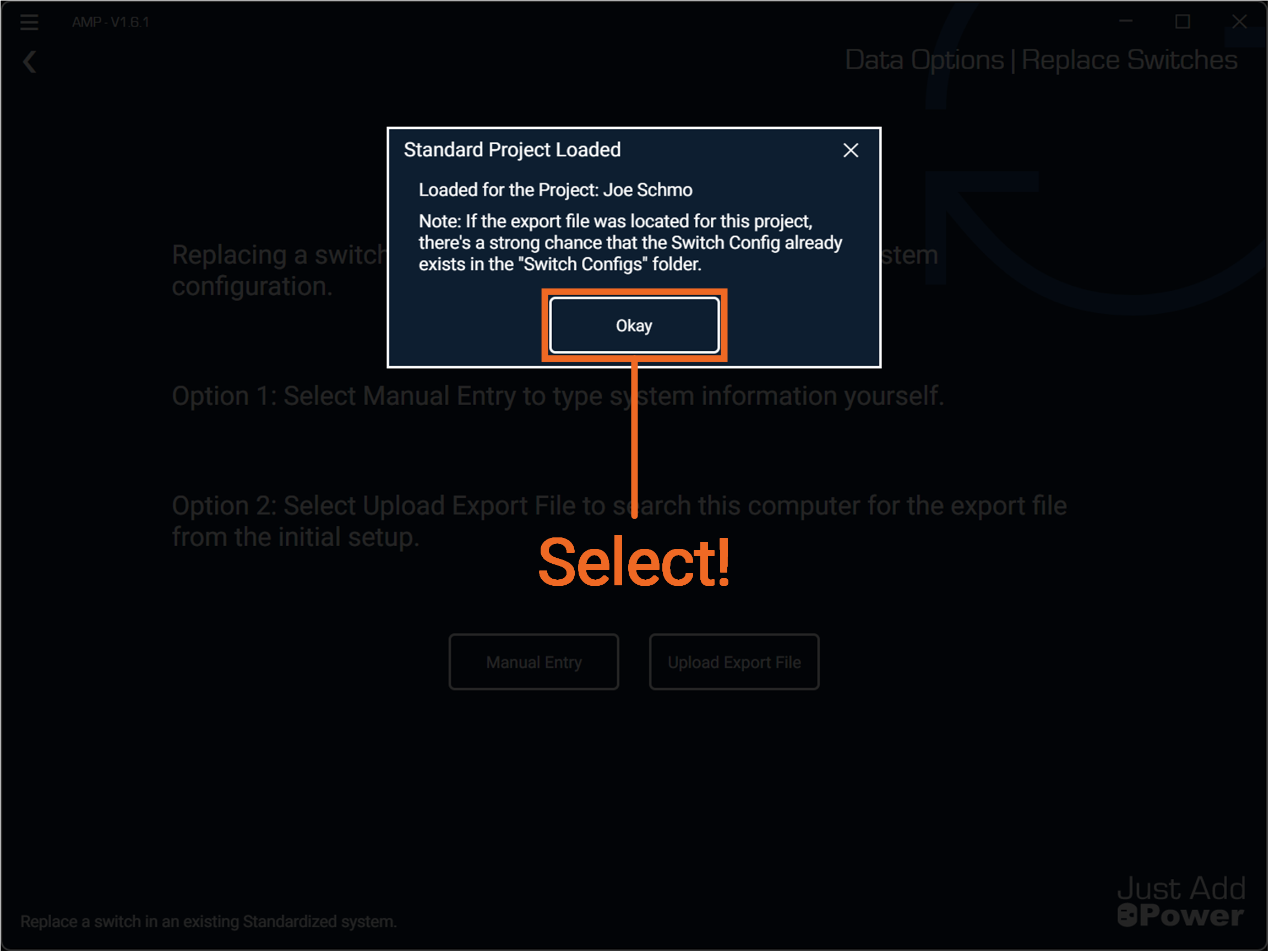
The Export file will now load with the system details for this project. Select "Okay"
-
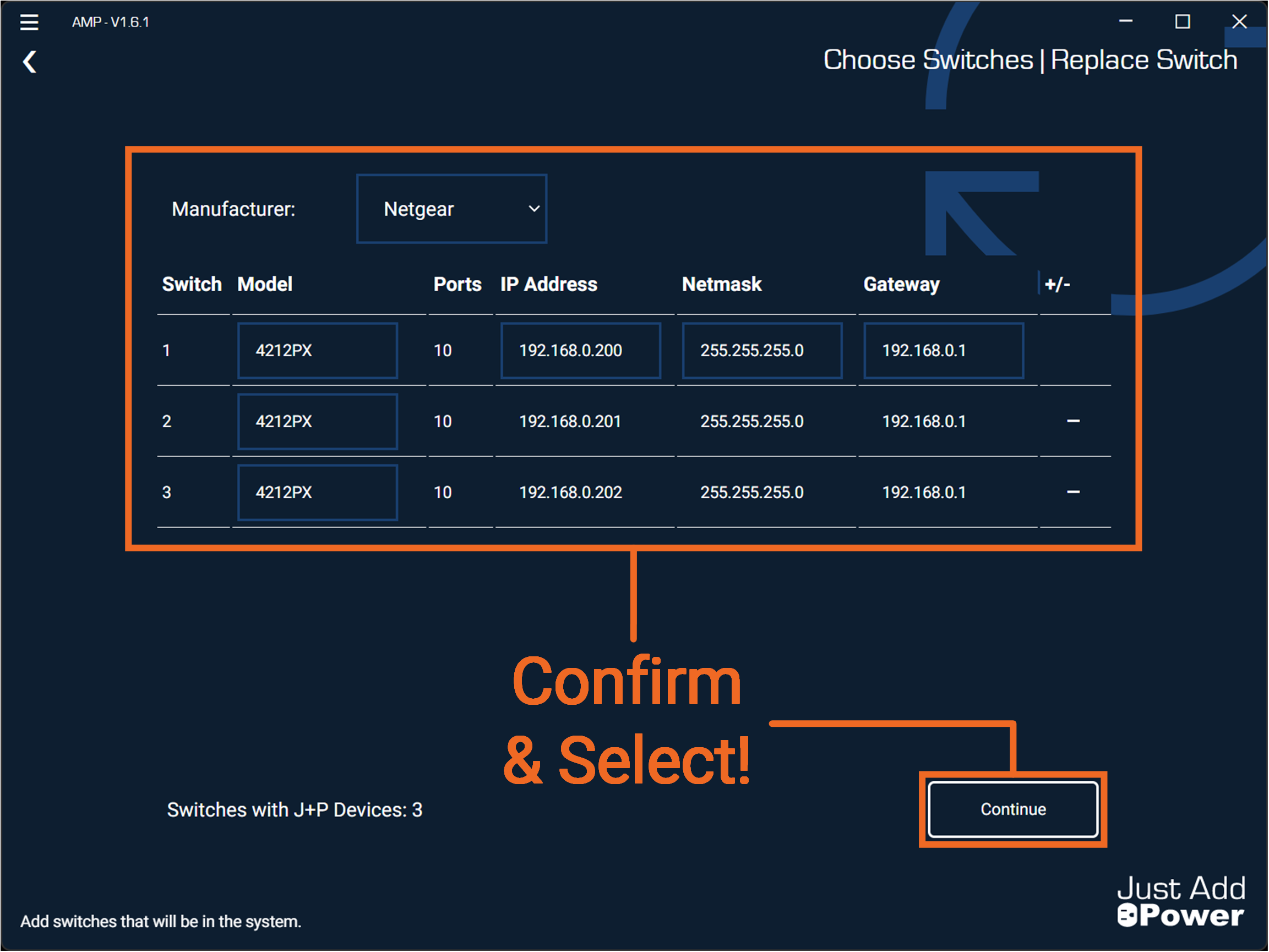
Confirm the switch information that appear are correct for your system. If the replacement switch is a different model than what was generated, change it by clicking the drop down for the correct switch. Select "Continue"
-
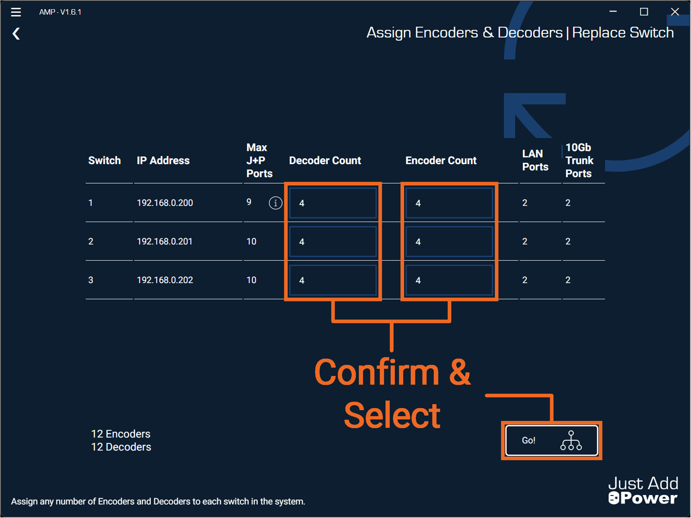
Confirm the Encoder & Decoder counts that appear for each switch are correct for your system. Select "Go!"
-
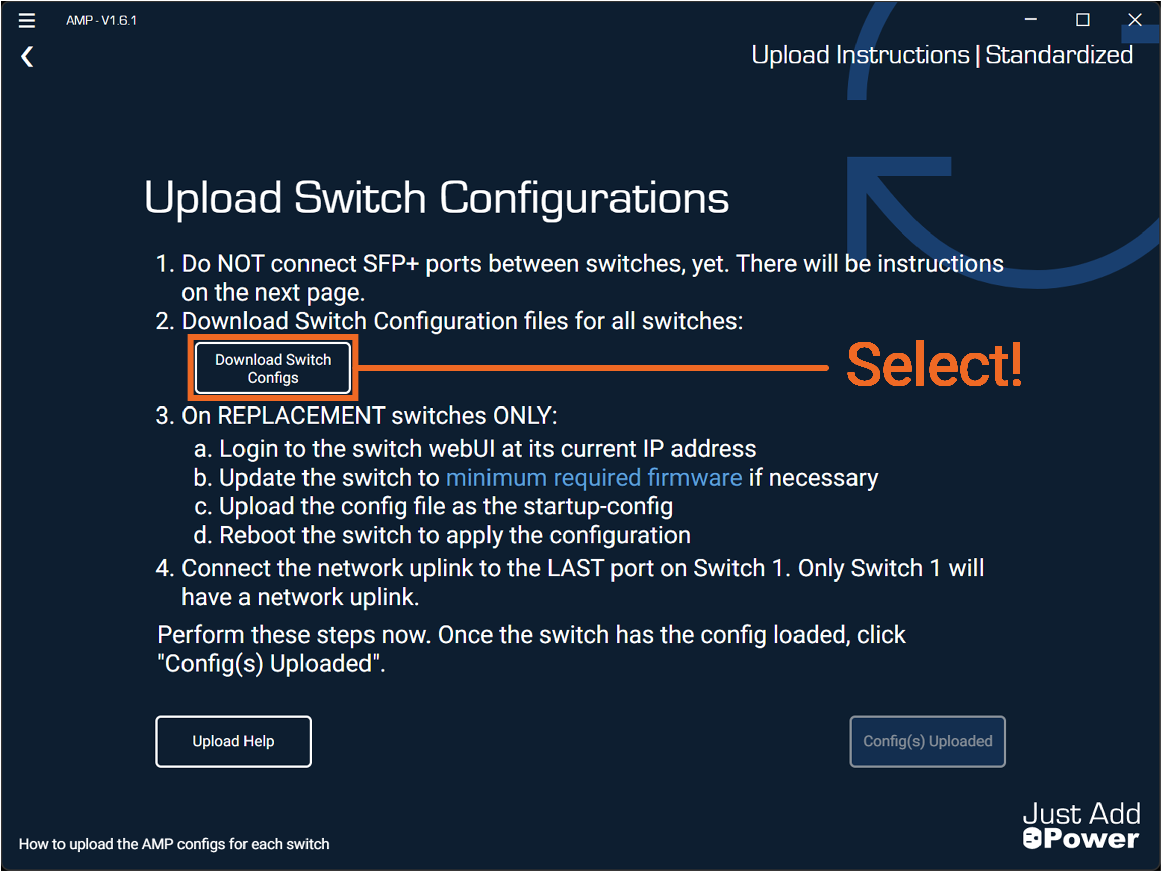
Select "Download Switch Configs".
-
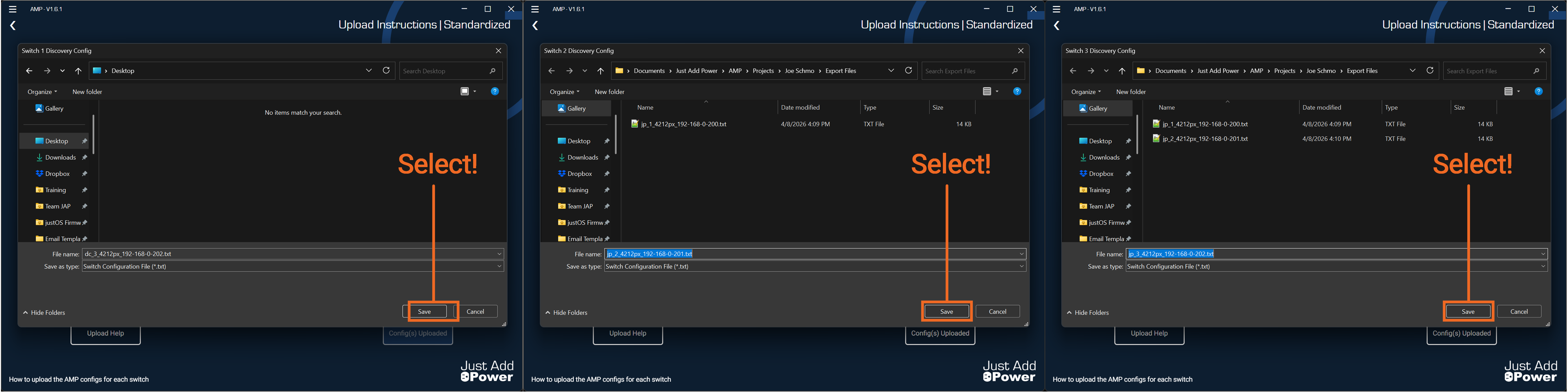
A Windows File Explorer will appear with the option to save the replacement switch configuration files. Select "Save". It is recommended to save these files in a place that is easy to locate.
For this example, we save the switch configurations for all three switches.
-
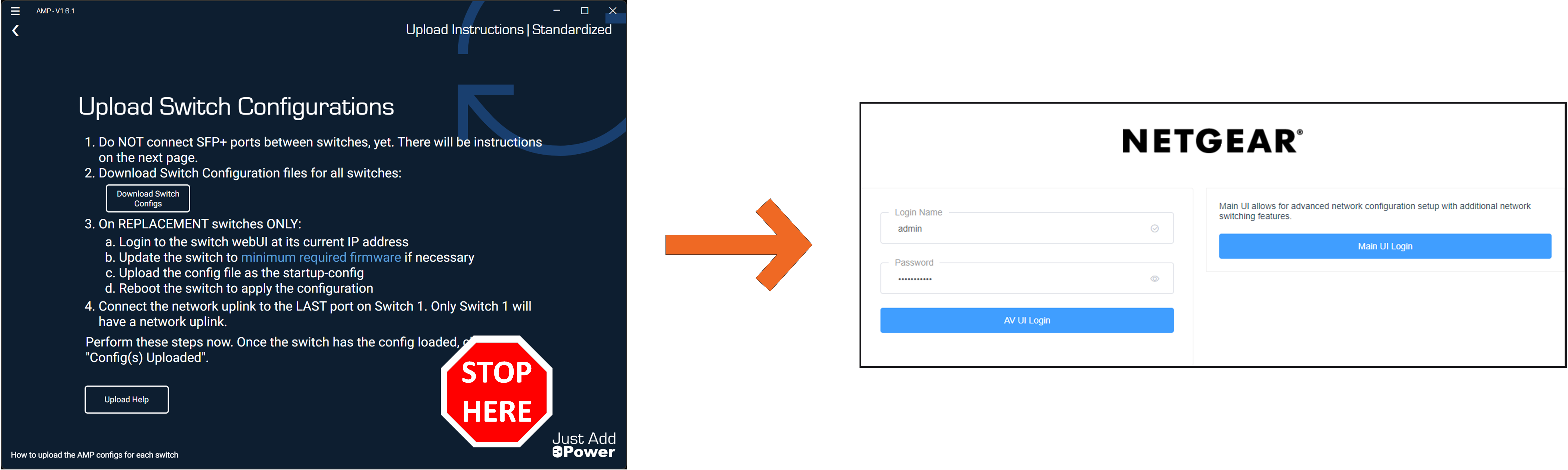
Do NOT continue with AMP! Navigate to the webUI of the replacement switch and Upload the associated configuration file you downloaded.
For this example, we are replacing the second switch in our three switch system.
-
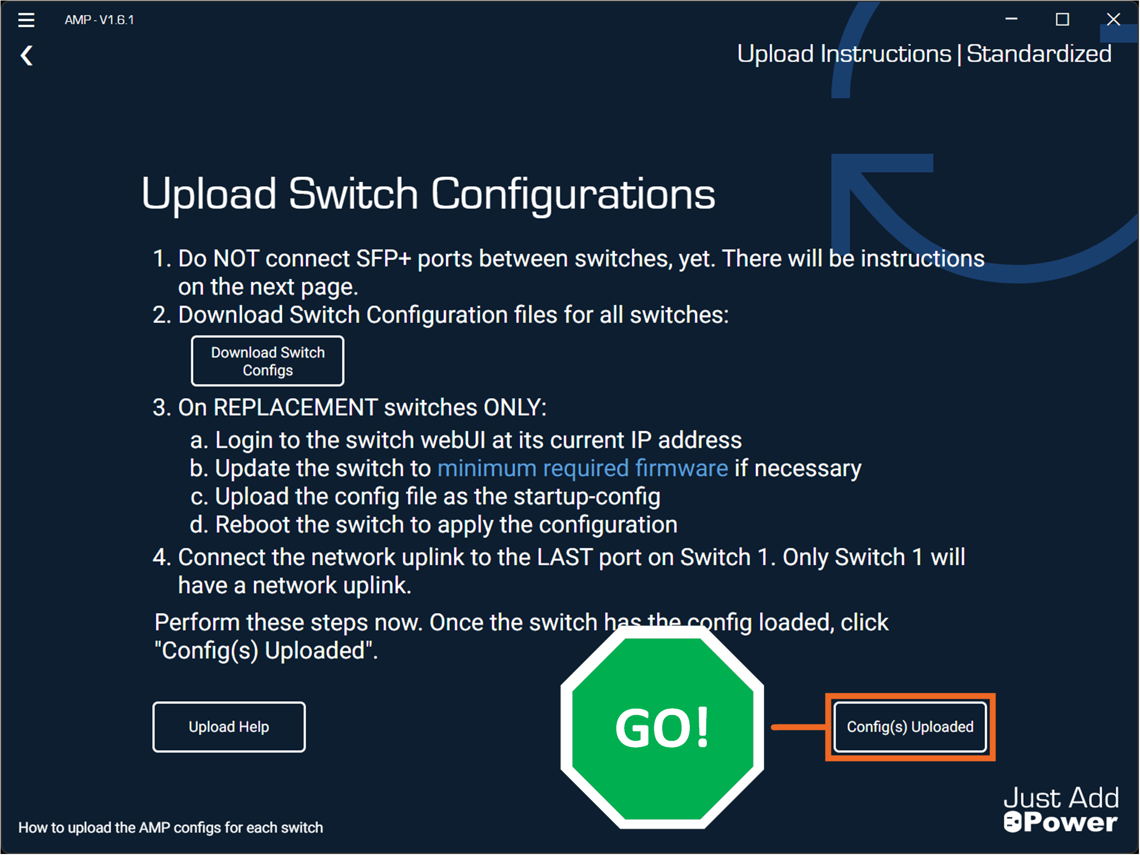
Return to AMP! Continue by selecting "Config(s) Uploaded"
-
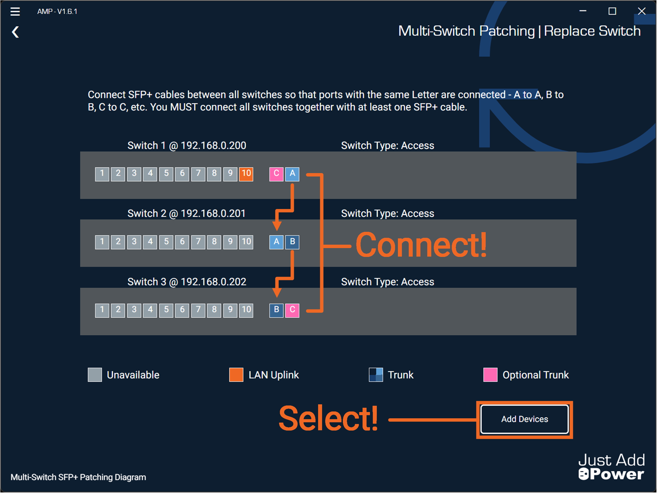
If you are running a multi-switch system, connect your SFP+ cables at this time and afterward select "Add Devices".
Note: Skip connecting SFP+ cables if the system is a single switch configuration.
-
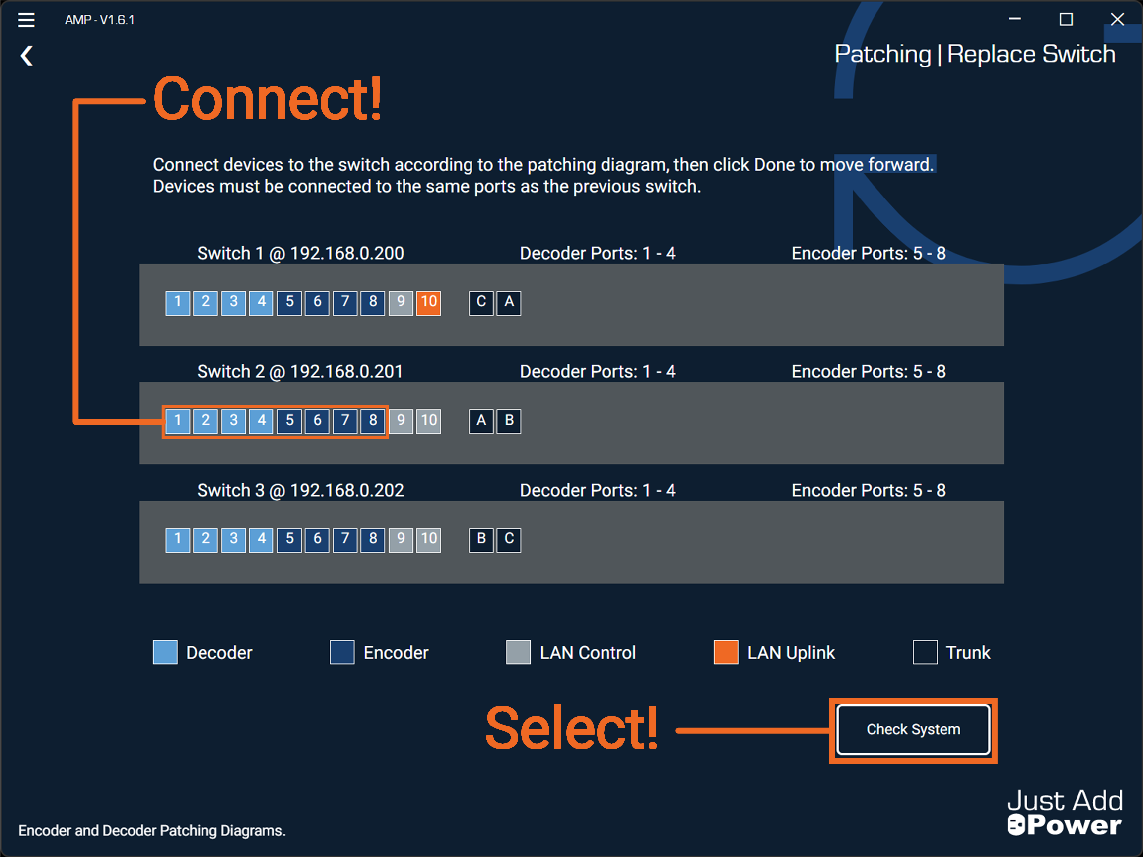
Connect the Encoders and Decoders back to the replacement switch. Afterward select "Check System".
-
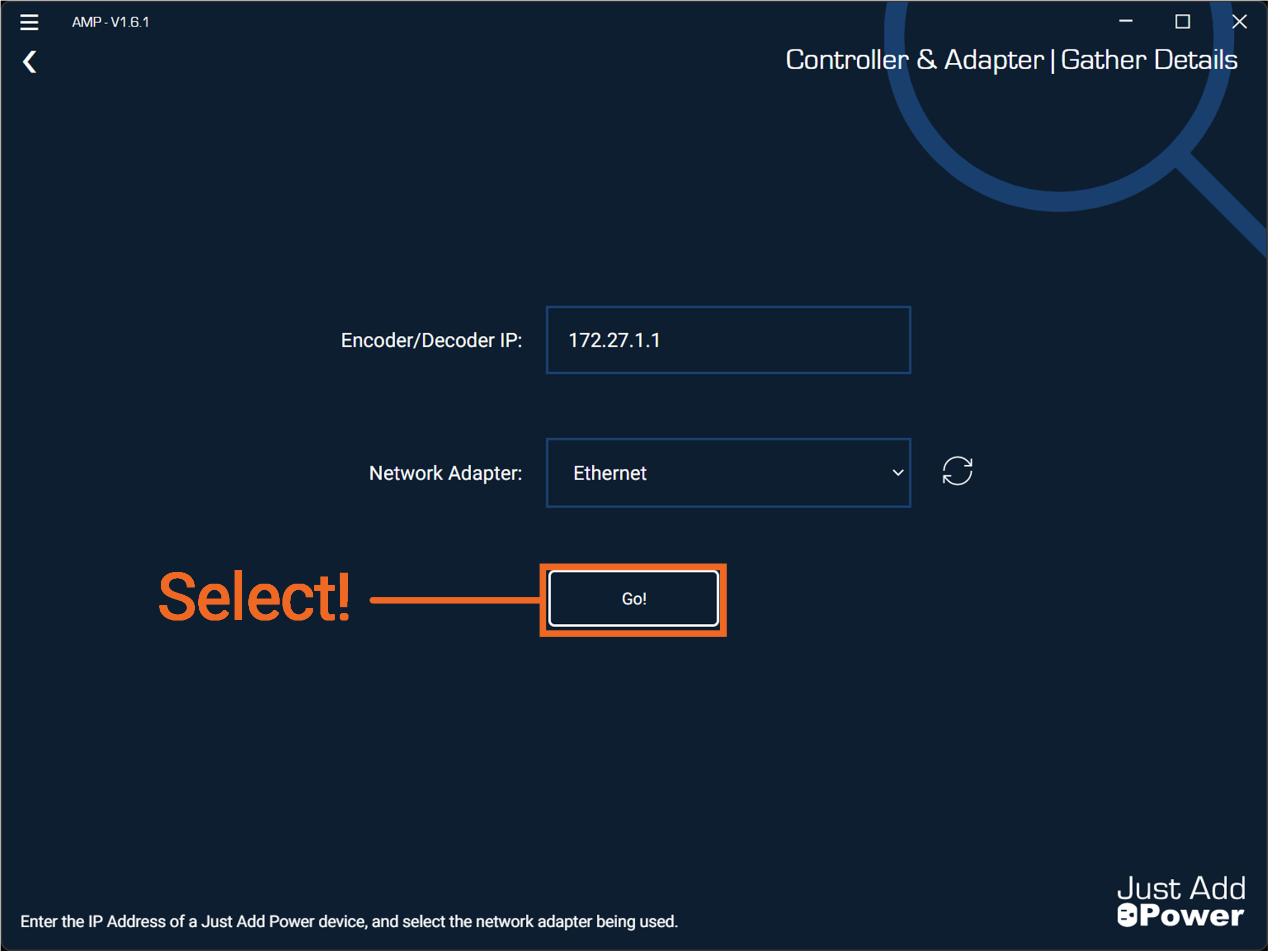
Confirm Encoder/Decoder IP is correct and active, then check if the network connection on the PC has access to the network with an active static route. Select "Go!" to continue.
-
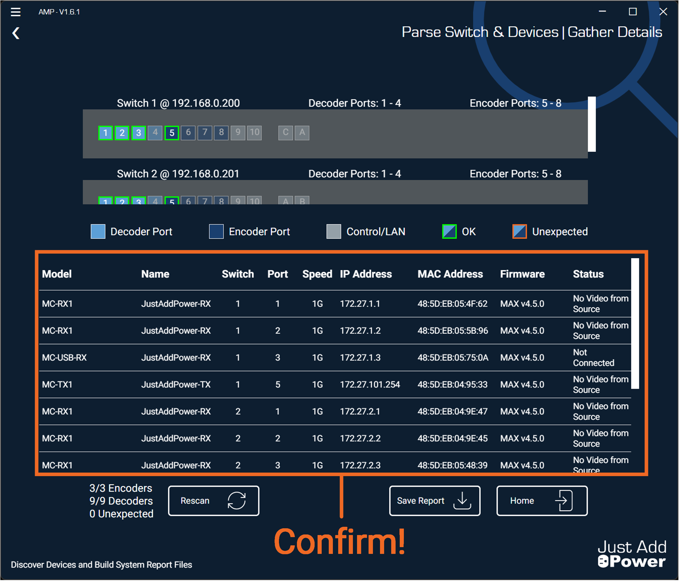
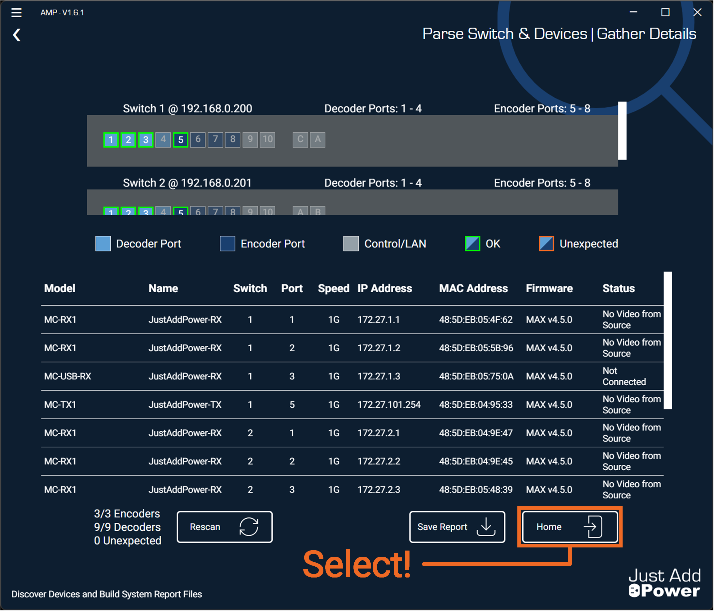
AMP will validate the system by confirming the replacement switch is operating with a valid configuration and that all devices are active and properly connected. Verify that all devices have been reconnected correctly.
-
Select "Home" to finish.
-
Done!
Part C: Upload Switch Configurations
Prepare the replacement switch so it is accessible on the network and updated to the latest firmware.
Warning: For Just Add Power systems with multiple switches, do NOT connect the SFP+ cables to the replacement switch until AMP instructs you.

