


Build a New Single-Switch System with AMP Standardized Configuration
Overview
Use AMP to configure a new Standardized Configuration system with one supported network switch. AMP generates the switch configuration, verifies the connected Encoders and Decoders, and configures the system for video distribution.
This procedure covers Omega Series, Ultra Series, MaxColor Series, and supported 2G Series systems operating in AMP 2G Legacy Mode. The selected switch model and required Encoder and Decoder counts determine the system's port assignments.
Build New overwrites the existing switch configuration. If you are expanding an established system with available Encoder or Decoder ports, follow Add New Devices On-site with AMP Standardized Configuration.
Walkthrough
Before You Begin
- Download and install AMP. Review the supported switch list and known issues linked on the download page.
- Confirm that the exact switch model and firmware meet the supported switch requirements for AMP Standardized Configuration.
- Confirm that the Encoders and Decoders are compatible with the intended system's series and operating mode.
- Have a Windows PC with a wired Ethernet adapter, suitable network cabling, and power for the devices.
- Obtain an available switch management IP address and the site's subnet mask and gateway settings.
- Have access to the switch webUI and its current login credentials. If repurposing a switch, retain a backup of its configuration and plan the service interruption before starting.
- Determine how many Encoder and Decoder ports are needed, including ports reserved for future expansion.
For a system containing 2G Series devices, review 2G Legacy Mode compatibility and limitations before selecting hardware and starting configuration.
Keep the supported switch and Just Add Power devices disconnected from the site network until AMP prompts you to connect them.
Start Build New
- Connect the PC to the site router or an existing Data Network switch using its wired Ethernet adapter.
- Open AMP and select Build & Expand for Standardized Configuration.
- Select Build New.
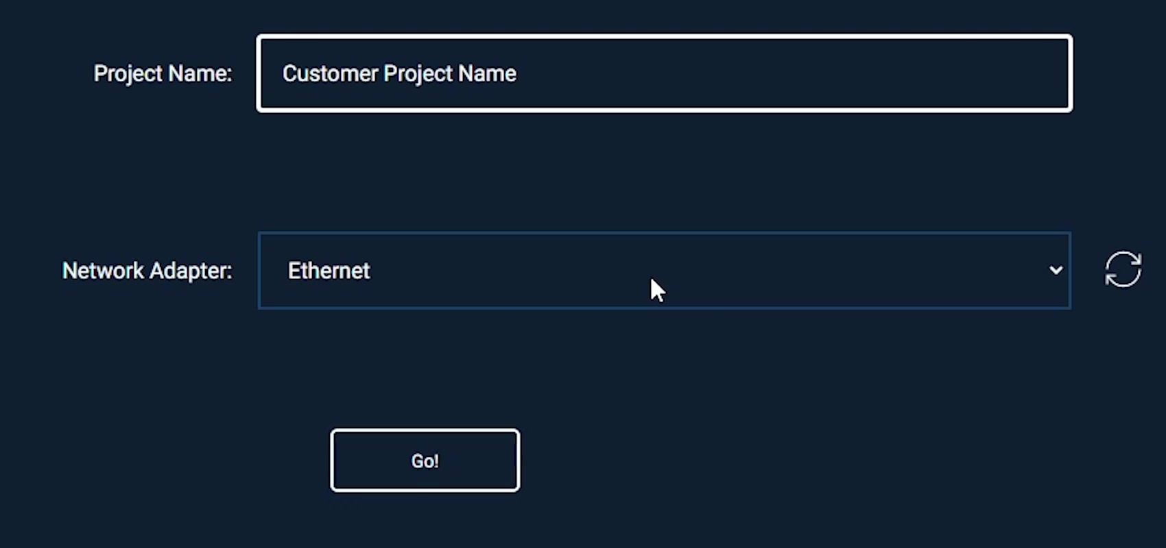
- Enter a project name for the installation.
- Select the PC's wired network adapter.
- Click Go!.
The PC connects to the existing site network at this stage. Connect the supported switch when prompted during discovery configuration.
Select the Switch and Assign Its IP Address
- Select the switch manufacturer.
- Select the exact switch model from the drop-down list.
- Enter the available management IP address assigned to the switch.
- Review the netmask and gateway that AMP fills automatically. Confirm that they match the site network.
- Click Continue.
This address is the switch's management IP address on the site network. AMP configures the Just Add Power device addresses later in the procedure.

Use an available address assigned for the switch by the site network administrator. The example 192.168.0.11 is not a required address. Check the automatically filled netmask and gateway rather than assuming they fit every site.
Allocate Encoder and Decoder Ports
- Enter the number of Decoder ports required.
- Enter the number of Encoder ports required.
- Include any additional ports to reserve for future Encoders or Decoders, within the switch's available capacity.
- Click Go!.
Plan for expansion now: Reserved Encoder and Decoder ports can remain empty during setup. Devices can be added to those ports later using Add Devices. An unused Data Network port is not an expansion port; adding more Encoder or Decoder ports later requires rebuilding the switch configuration.
For an explanation of Encoder, Decoder, and Data Network port assignments, see Switch Configuration Guidelines for AMP Standardized Systems.

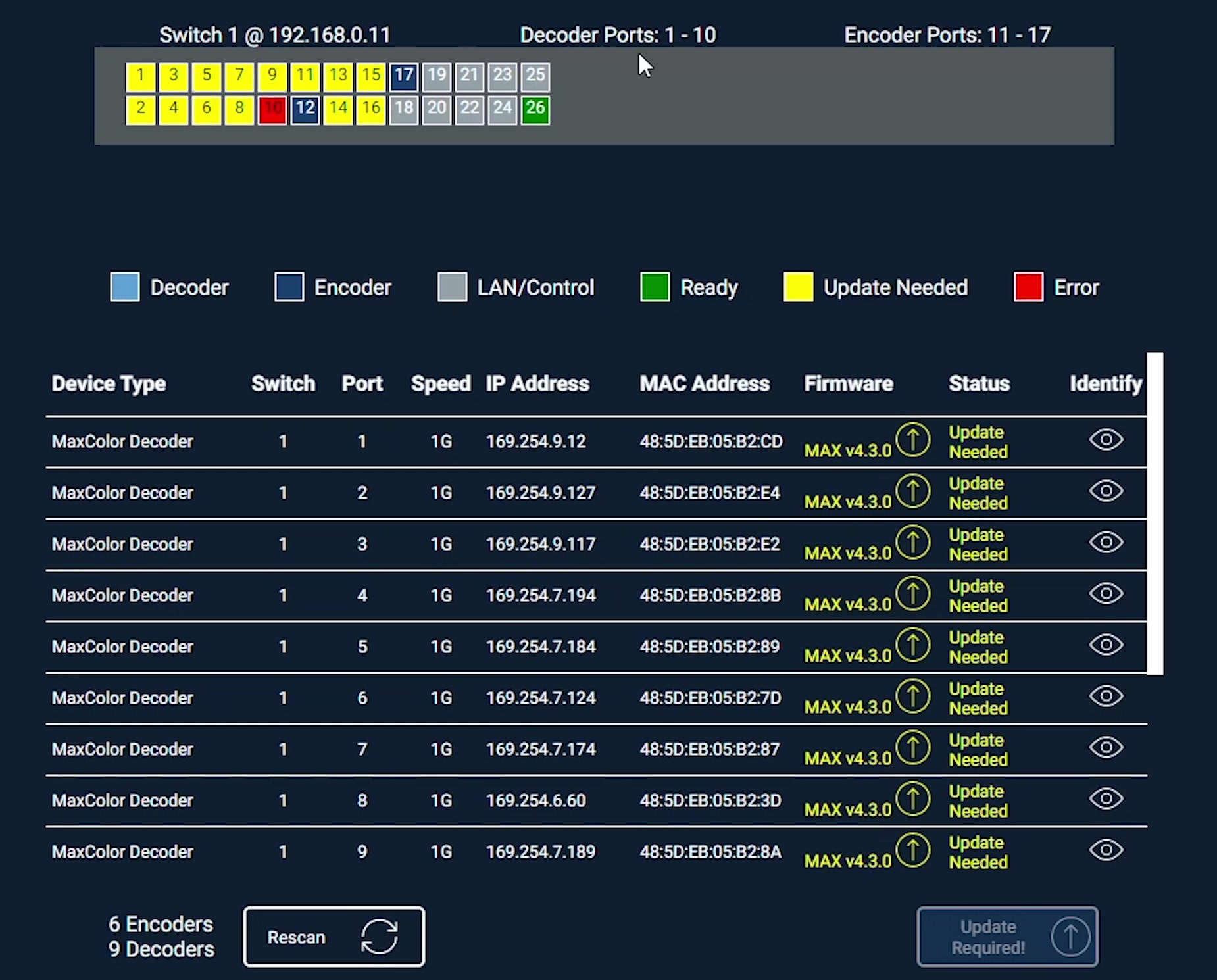
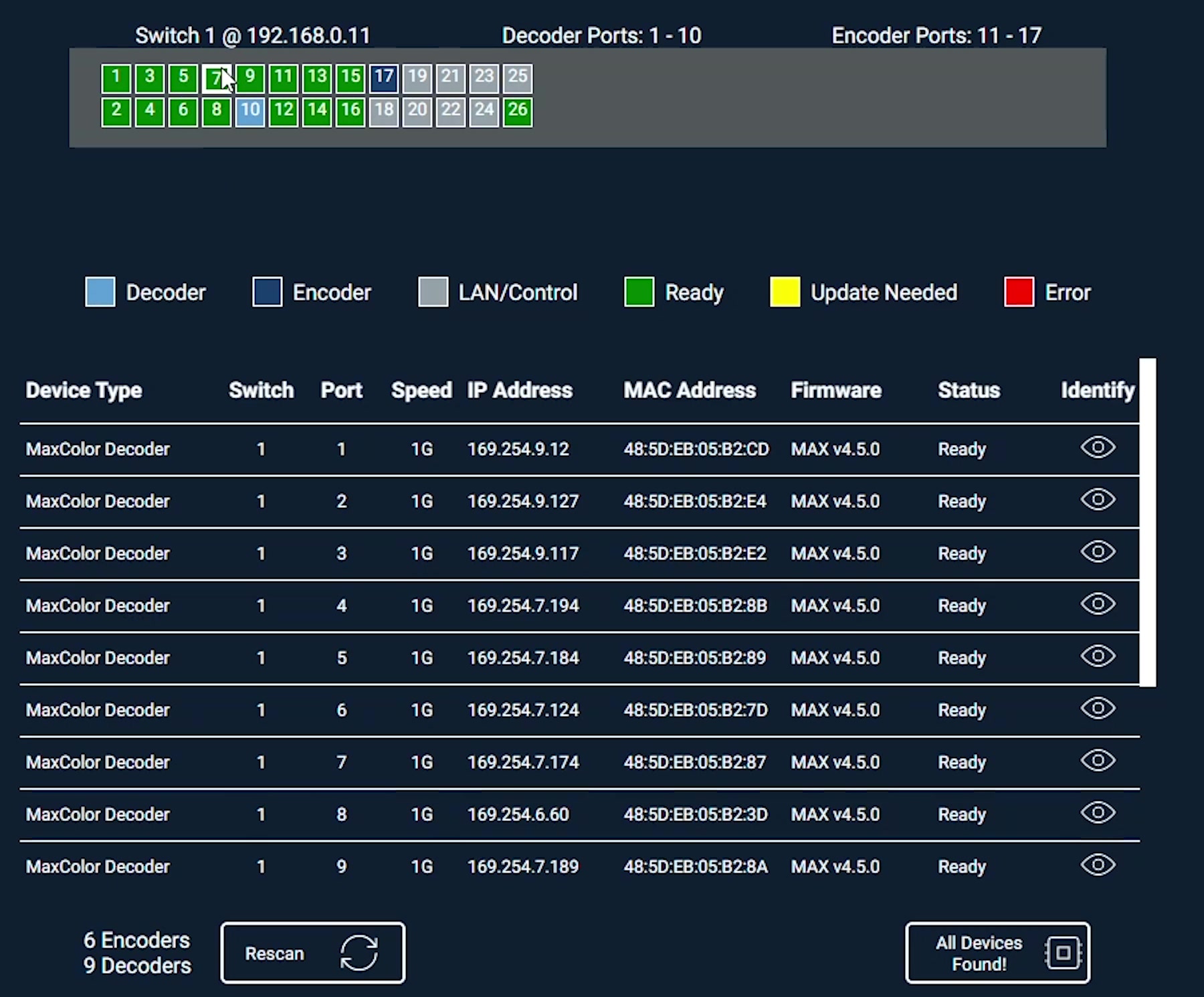
Example: Installing nine Decoders and six Encoders while reserving one port for each means entering 10 for Decoder Count and 7 for Encoder Count. On this example switch, Decoders occupy ports 1-10, Encoders occupy ports 11-17, and the network uplink uses port 26. Decoder port 10 and Encoder port 17 remain empty initially. Use AMP's diagram for your selected switch.
Decoder ports precede Encoder ports. Increasing the Decoder allocation later can shift the physical Encoder connections, which is why reserving expansion ports during the initial build matters.
Upload the Discovery Configuration
The discovery configuration prepares the switch for AMP to identify and configure the connected devices. Upload this file before connecting the Encoders and Decoders.
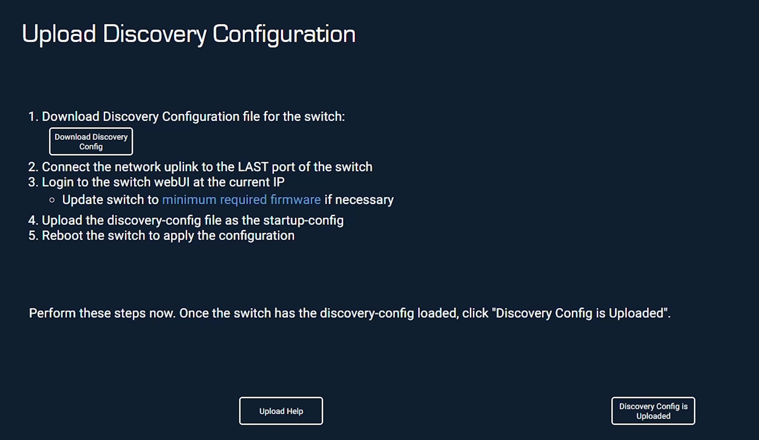
- Click Download Discovery Config in AMP and save the file somewhere easy to find.
- When prompted, connect the switch's last designated network uplink port to the existing site network. Use the port identified by AMP for the selected model.
- Log in to the switch webUI at its current IP address.
- Upload the discovery configuration file using the switch-specific instructions provided by AMP.
- Save the configuration and reboot the switch as directed.
- Wait for the switch to finish rebooting.
- Return to AMP and click Discovery Config is Uploaded.
Netgear M4250: Upload Standardized AMP configuration files through the Main UI. Follow Upload Switch Config to Netgear M4250 Series Through Main UI Login. The documented warning advises against uploading these files through the AV UI because the switch can become inaccessible.
For another switch family, select Upload Help in AMP and follow the procedure for that model. Menu names and upload methods differ between manufacturers. After the configuration is applied, use the switch address assigned for this project.
This completes the discovery stage only. Continue through device discovery and configuration; AMP applies the final switch configuration later in this workflow.
Connect the Encoders and Decoders
AMP displays a patching diagram showing the port assignments for the selected switch and system size. Use these assignments when connecting the devices.
- Confirm that the site network connection is in the designated uplink port.
- Connect the Decoders to the labeled Decoder ports.
- Connect the Encoders to the labeled Encoder ports.
- Provide suitable PoE or supported external power to each device and allow it to complete startup.
- Leave reserved expansion ports empty if their devices are not being installed yet.
- Leave gray ports empty during setup. Data Network devices can be connected to these ports after configuration is complete.
- Click Discover when all devices being installed are connected.
Sources and displays can be connected before or after configuration. Keep each Encoder and Decoder connected to its assigned switchport throughout setup.
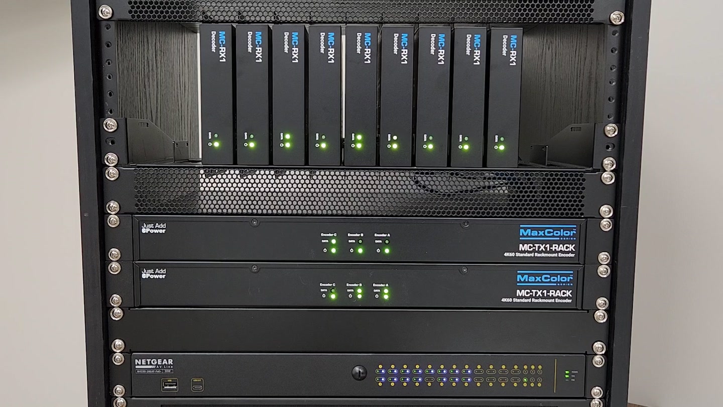
For Omega Series, Ultra Series, and MaxColor Series devices in normal series operation, a device ready for discovery has a solid Power LED and a blinking Data LED before an HDMI source is connected. An active, compatible HDMI source can change the Encoder's Data LED to solid green while the Decoder's Data LED continues blinking before system configuration is complete. During AMP identification, the Data LED turns off; confirm the device in AMP's list.
For additional information about these indicators, see Understand Power and Data LED Behavior for Omega Series, Ultra Series, and MaxColor Series. For 2G Legacy Mode systems, use the 2G Legacy Mode troubleshooting guide.
Verify the Discovered Devices
Review AMP's discovery results. Confirm that every device being installed is detected in the correct port. Resolve any reported connection or firmware issues before applying the configuration.
| Port Color | Meaning During Discovery | Required Action |
|---|---|---|
| Red | An issue requires correction, such as a device connected to the wrong port. | Review the issue shown in AMP, correct it, and click Rescan. |
| Yellow | The device requires a firmware update. | Complete the firmware update before continuing. |
| Blue | The port is empty. | Leave it empty if reserved for expansion. If a device should be present, check its power and connection, then rescan. |
| Green | The device has passed the discovery checks. | Confirm that it is connected to the intended port. |
Update Required Firmware
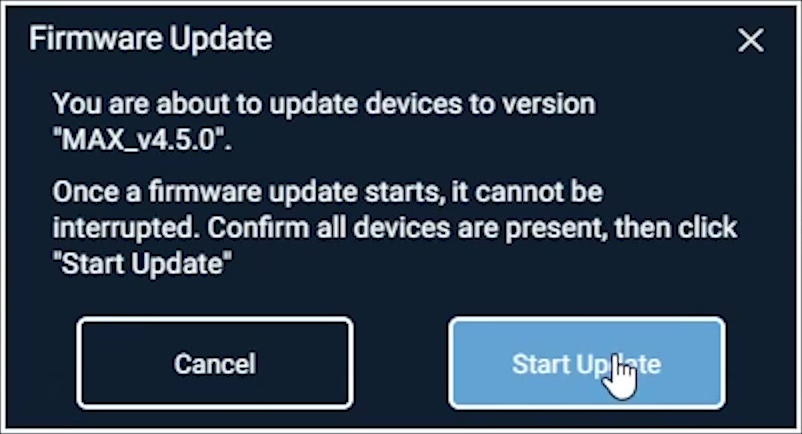
- If AMP identifies devices requiring firmware updates, click Update Required!.
- Review the firmware target shown by AMP, then click Start Update.
- Wait for the updates and any required device restarts to complete.
- Review the discovery results again.
Do not interrupt a firmware update: Keep AMP open and maintain power and network connections to the PC, switch, and devices until the update is complete.
When all devices being installed are detected and their ports are green, click All Devices Found!. Ports intentionally reserved for expansion can remain blue.
Configure the Devices
- Optionally, name the devices according to their connected source, display, or location.
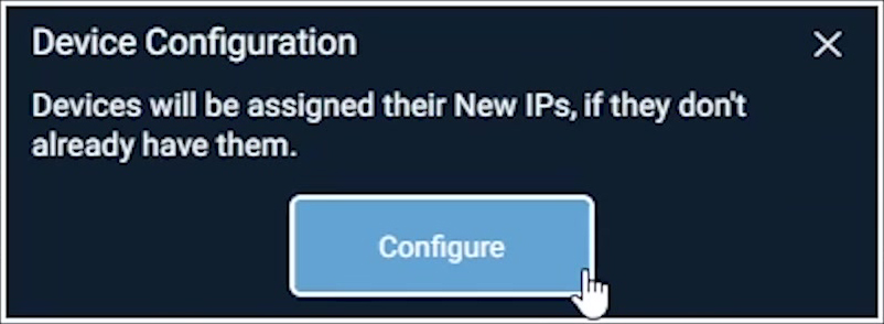
- Click Configure Devices, then Configure.
- Wait while AMP applies the device settings and verifies configuration.
- Confirm that all configured devices show green before proceeding.
Do not interrupt configuration: Keep AMP open and maintain power and network connections throughout device and switch configuration. Wait for AMP to confirm completion before changing connections.
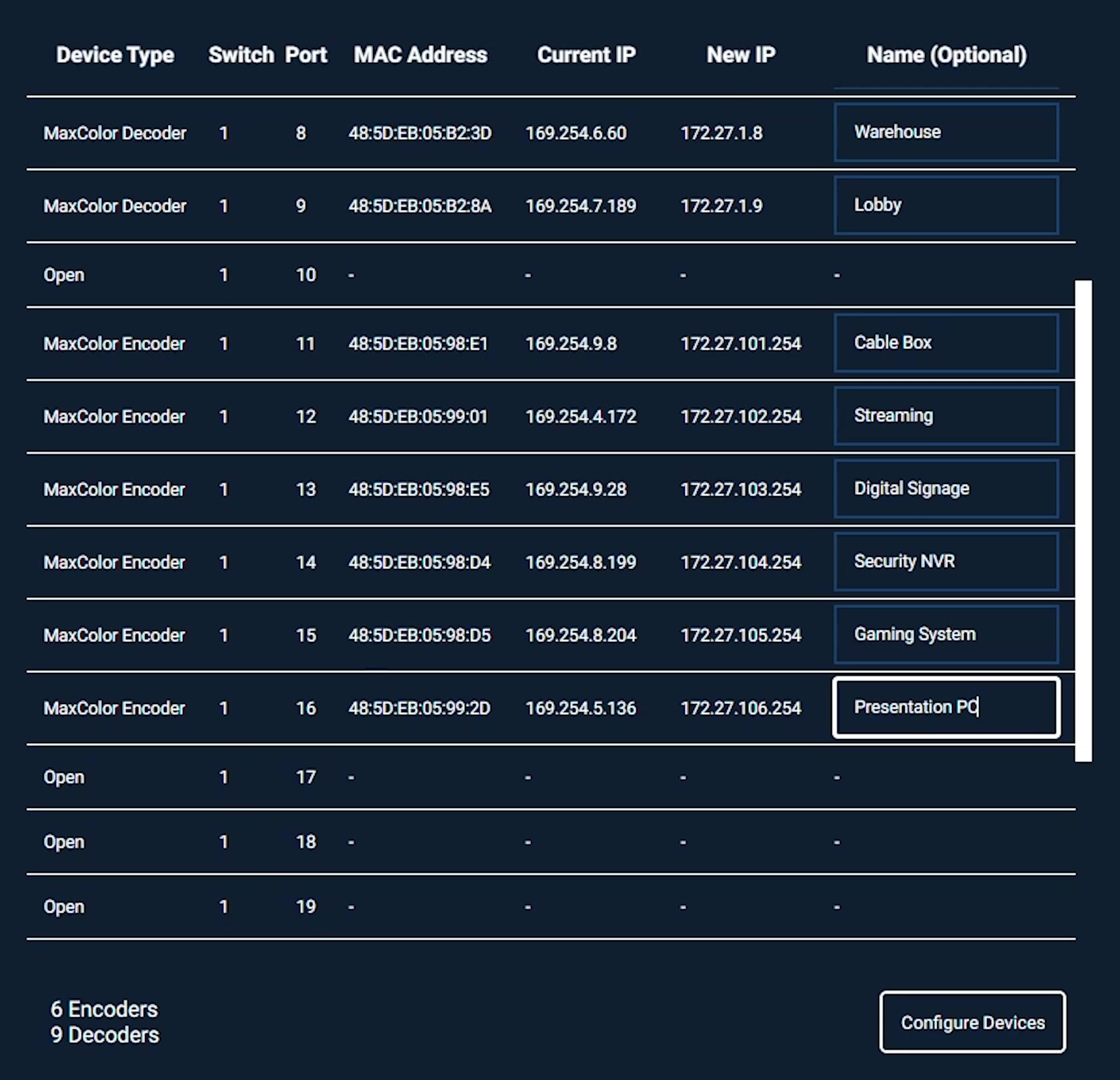
Use names that identify the source, display, or installation location. Review the Switch, Port, and New IP columns before applying settings. The names help document the system; configuring devices does not complete the control system programming.
Complete the Switch Configuration
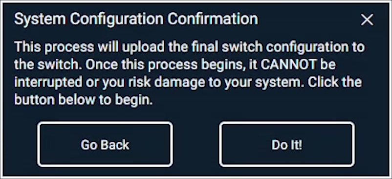
After the devices are configured and verified, AMP applies the final switch configuration for normal system operation.
- Click Configure Switch, then review the System Configuration Confirmation dialog and click Do It!.
- Wait while AMP configures the switch.
- Continue when AMP confirms that the system configuration is complete.
Save Documentation and Configure Routing
- Click Save Report File to download the system documentation from AMP.
- Keep the report with the installation records. It contains the device assignments, IP addresses, and information needed for routing and control system setup.
- Use the report's static route information to configure access from the Data Network to the Just Add Power Device Network.
- Click Finish! to complete the AMP workflow.
Routing allows equipment on the Data Network to communicate with the configured Just Add Power devices. A router static route is the recommended permanent access method. Follow Static Route Options for Accessing the Just Add Power Device Network for instructions and alternatives when router static routing is unavailable.
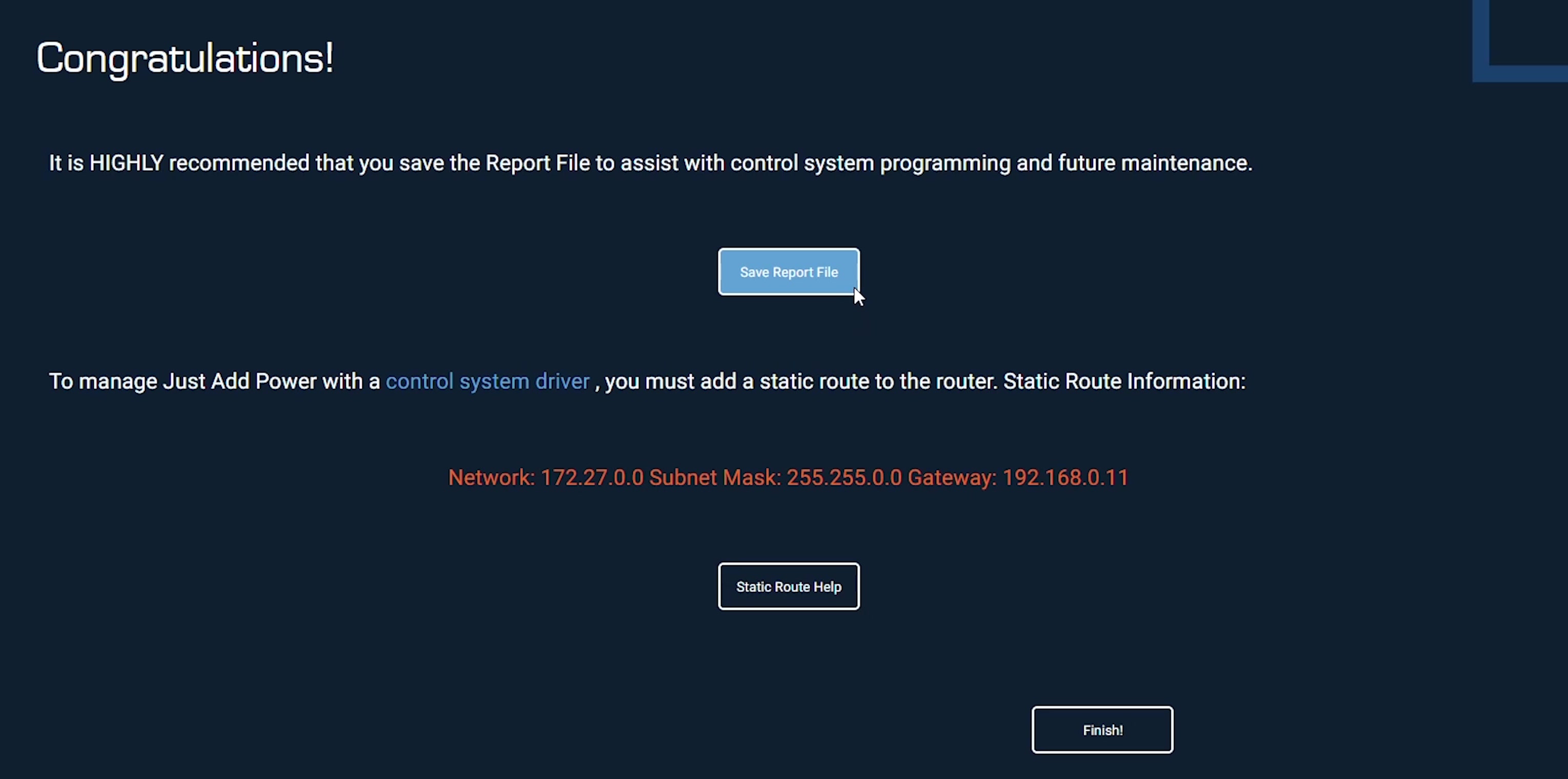
The route's Destination Network and Netmask identify the Just Add Power Device Network. Its Gateway is the Just Add Power switch's management IP address on the Data Network. These route fields are different from the switch's own default gateway setting entered earlier.
Copy the values generated for this installation. A control processor gateway setting provides access for that processor only; use the routing guide when the PC or other authorized network equipment also needs device access.
Verify the System
After a successful new build, Encoder 1 is initially selected on the Decoders. With compatible sources connected, the Power and Data LEDs should be solid under default LED behavior. Confirm the actual picture and audio on each display; solid LEDs alone do not verify the complete HDMI path.
- Connect the sources, displays, and any additional audio, USB, or control connections required for the installation.
- Confirm that each source produces video and audio through a compatible Decoder and display.
- Confirm that each Decoder and display can receive a known-working source.
- Complete control system programming using the assignments in the AMP report.
- Test source switching from the customer's control interface.
- Verify any additional features required for the installation.
For continued video, audio, device access, or switching problems, use the troubleshooting guide for the system's operating mode:
Troubleshooting
The Switch Rejects the Discovery Configuration
- Compare the selected manufacturer and exact model with the physical switch.
- Confirm the switch firmware meets the applicable requirements, including known restrictions linked from the AMP download page.
- Use the discovery file generated for this project and the upload method specified for the switch family. For Netgear M4250 Standardized files, use the Main UI procedure.
Device Discovery Does Not Complete
- Determine whether all devices, one device, or a group of devices is missing. For all devices, check the PC's selected wired adapter, network uplink, and whether the Discovery Configuration upload and reboot completed.
- For an individual device, compare its cable connection with AMP's patching diagram. Confirm suitable power and allow startup to complete.
- For a suspect installed cable path, connect the device directly to its assigned port with a short, known-working patch cable. If discovery works, inspect the cable run, terminations, and intermediate connections.
- Resolve red port errors, click Rescan, and complete required firmware updates. Leave only intentionally reserved device ports empty.
Video Works but Network Control Does Not
Check routing from the equipment that cannot connect, using this installation's report values. Then compare the control system's device addresses and input/output assignments with the report. Successful video distribution does not establish that the PC or control processor can reach the Device Network.

