[AMP] [Standardized] Single-switch JADConfig Conversion
Overview
JADConfig - released in 2011 and deprecated in 2022 - has assisted countless Installers with configuring Just Add Power systems. Starting with a group of unconfigured hardware, an Installer can build a fully-functional Just Add Power AV over IP matrix switching system in about 30 minutes.
JADConfig systems are still supported and we encourage systems built with JADConfig to remain that way. However, end-of-life or unavailability of switch replacements may make it necessary to convert to Advanced Matrix Programmer (AMP) for the system to remain functioning.
This article provides the instructions for certain legacy installations configured using JADConfig to transition to AMP.
Requirements
- System contains exclusively 2G Omega or 3G Ultra devices on firmware Bx.x.x
- 2G devices are not supported by AMP. 2G Omega or 3G Ultra devices running in 2G Mode are not supported by AMP.
- System is currently built using JADConfig standards. If JADConfig built the system, it meets all of these standards.
- The system only has one switch with Just Add Power devices connected to it
- The switch in the system after the conversion - either the original switch or the replacement - is listed here as a compatible switch for AMP VLAN and has enough ports for all devices
Convert Switch and Devices
We recommend following these steps carefully, as converting from JADConfig to AMP VLAN requires device labeling, cables disconnecting, wires moving, cables reconnecting, control system drivers updating, and IPs changing.
- Get an initial inventory of the system. The Takeover Job Assistance article will assist with finding these details:
- Switch manufacturer and model
- Switch IP address, subnet mask, and default gateway (default gateway is typically the IP address of the router)
- Number of active Transmitters
- For each active Transmitter, record the Transmitter Number, the port on the switch it is currently connected to, and the name of the source it is connected to
- Number of active Receivers
- For each active Receiver, record the Receiver Number, the port on the switch it is currently connected to, and the name of the display it is connected to
- Number of ports configured for Transmitters (this may be different than active Transmitters, as there may be empty ports on the switch that were created for future expansion)
- Number of ports configured for Receivers (this may be different than active Receivers, as there may be empty ports on the switch that were created for future expansion)
- Label the network cables connected to the switch according to Data connection, Transmitter Number, or Receiver Number
- Before the conversion, port 1 is connected to the data network. Label this cable "Network Uplink"
- Transmitter 1 is connected to port 2. Label this cable "Transmitter 1".
- Continue for all Transmitters.
- Receiver 1 will be connected to the switch, though the port will be different depending on the number of Transmitters. Once you identify it, label the cable "Receiver 1"
- Continue for all Receivers.
- HDMI cables can remain connected throughout this process. Only the network cables will be moved.
- If the same switch is being used after the conversion, jump to Step 5
- If there is a replacement switch being installed, disconnect all cables from the old switch and install the new switch in its place. Do not connect any network cables to the new switch yet.
- Connect the "Network Uplink" cable to the last port of the switch. (Ignore SFP ports)
- Run AMP VLAN and follow the program to input the details recorded earlier:
- Switch manufacturer and model
- Switch IP address, subnet mask, and default gateway
- Upload the discovery configuration to the switch (instructions here)
- Input the Number of Receivers and Number of Transmitters that corresponds to the number of PORTS configured for Transmitters and Receivers. This count will include both active and empty ports.
- When the switch patching diagram appears, connect Transmitter and Receiver ports to the switch
- Connect the "Receiver 1" network cable to port 1
- Continue for all Receivers in ports 2 and up
- Connect the "Transmitter 1" network cable to the first Transmitter port. This port will be different depending on the number of Receivers.
- Continue for all Transmitters
- It is important that "Receiver 1" from the JADConfig system remains "Receiver 1" in the AMP VLAN system. The control system driver will read both of them as Receiver 1, even though they are connected to different ports. Connecting devices so they keep the same Receiver/Transmitter numbering will save time during the control system update.
- For example, the images below show the same system with 10 Transmitters and 10 Receivers. The top image is JADConfig port connections and the bottom image is AMP VLAN port connections.
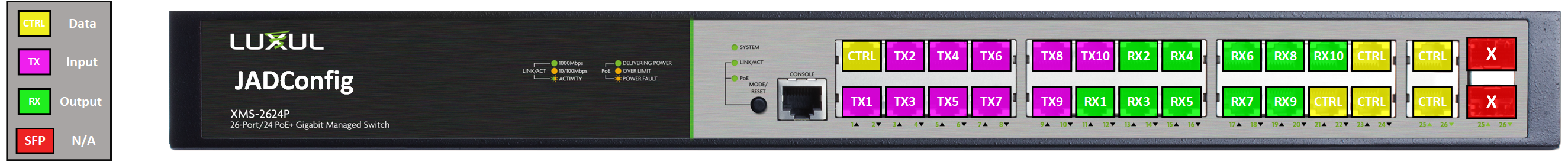
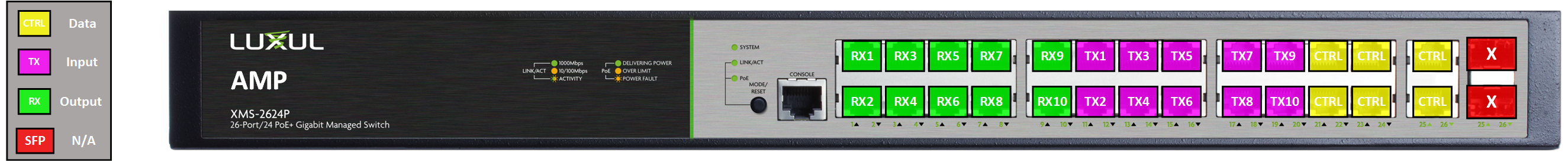
| Device |
Old Port |
New Port |
| Network Uplink |
Port 1 |
Port 26 |
| Transmitter 1 |
Port 2 |
Port 11 |
| Transmitter 2 |
Port 3 |
Port 12 |
| Transmitter 3 |
Port 4 |
Port 13 |
| Transmitter 4 |
Port 5 |
Port 14 |
| Receiver 1 |
Port 12 |
Port 1 |
| Receiver 2 |
Port 13 |
Port 2 |
| Receiver 3 |
Port 14 |
Port 3 |
| Receiver 4 |
Port 15 |
Port 4 |
- Continue with AMP VLAN until it is finished. All Just Add Power devices will be re-assigned new IP addresses during this process.
- Save the Report File when asked to do so. This is the most important piece of documentation for the system, and will be helpful when updating the control system driver.
- Video from Transmitter 1 will show on all Receivers in the system.