


Overview
Just Add Power 2G Series, Omega Series, Ultra Series, and MaxColor Series devices have a 3-pin debug port used with an RS232 debug cable for DeBrick device recovery. This article shows where to find the port and provides the cable pinout.
Debug Port Location
On Omega Series, Ultra Series, and MaxColor Series devices, the debug port is accessible from the bottom of the case.

On earlier 2G Series devices, the debug port is inside the case, on the top side of the circuit board.

Cable Pinout
The 3-pin debug connection carries RS232 transmit, receive, and ground. Use the diagrams below to identify the pins and assemble the cable.

A common debug cable uses a Molex PHR-3 connector at the device end and a DB9 connector at the computer end. A computer without a serial port also requires a USB-to-serial adapter.

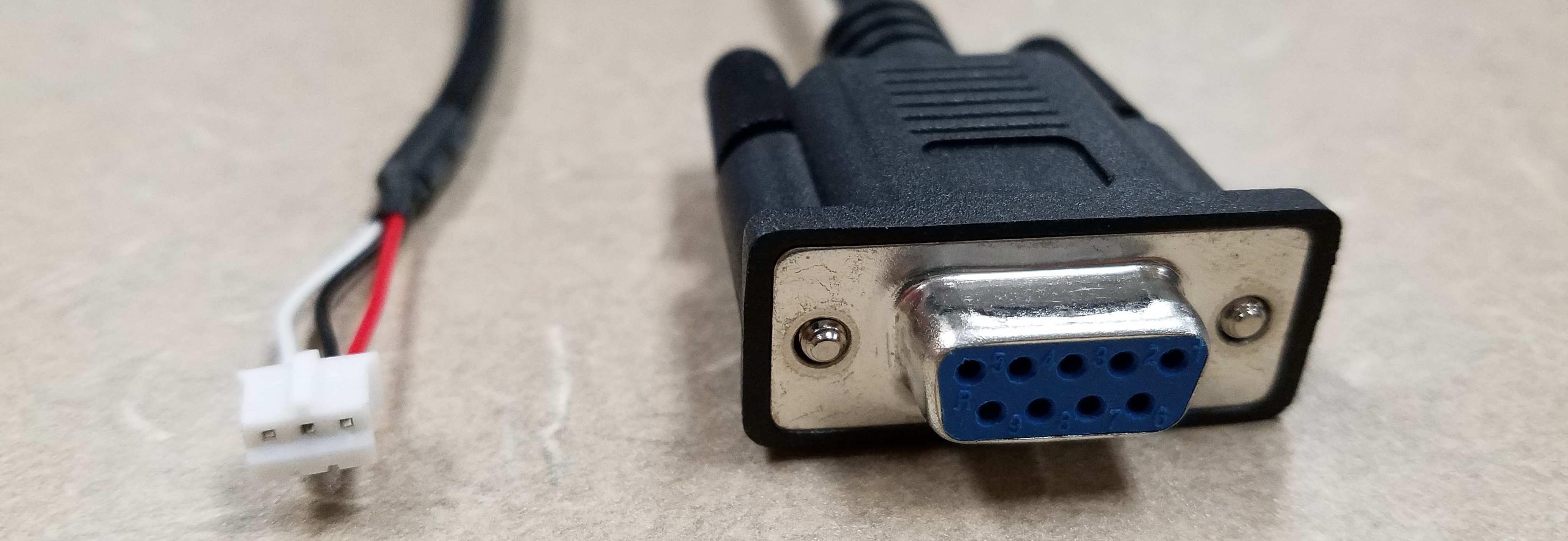
Get a Cable
Build a cable using the pinout and wiring diagram above, or request a debug cable from Just Add Power Technical Support. For the recovery procedure and other required hardware, see DeBrick: Recover a Just Add Power Device.

