


IR Control Using the Flux Dongle V1 and V2 (2G Legacy Mode, Omega, and Ultra Series)
Overview
The Flux Capacitor IR Dongle converts the RS232 port on a Just Add Power device into an IR blaster. Use this article to identify your dongle, configure the connected Just Add Power device, and send IR commands to a source or display.
These instructions cover V1 and V2 dongles on supported 2G Series, Omega Series, and Ultra Series devices, including compatible devices running L Series firmware in AMP 2G Legacy Mode.
Identify Your Dongle
Check the dongle's marking and status LED before selecting its setup instructions.
| V1 | V2 |
|---|---|
 |
 |
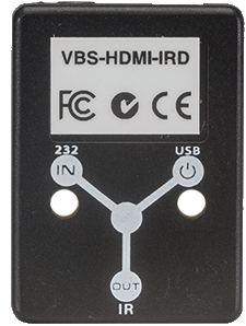
IR Dongle V1
V1 has no V2 marking and no status LED.
Deprecated hardware: V1 is the legacy dongle revision. Just Add Power continues to support systems using this hardware. Use the V1 settings when maintaining an existing V1 installation.
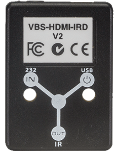
IR Dongle V2
V2 has V2 printed on the housing and a red status LED.
Red LED Status
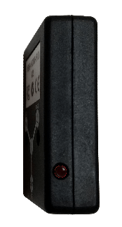
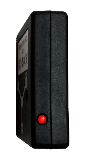
The illustrations below simulate the V2 status light. Flicker timing is illustrative, not a measured flash pattern.
| Off | Solid Red | Flickering Red |
|---|---|---|
 |
 |
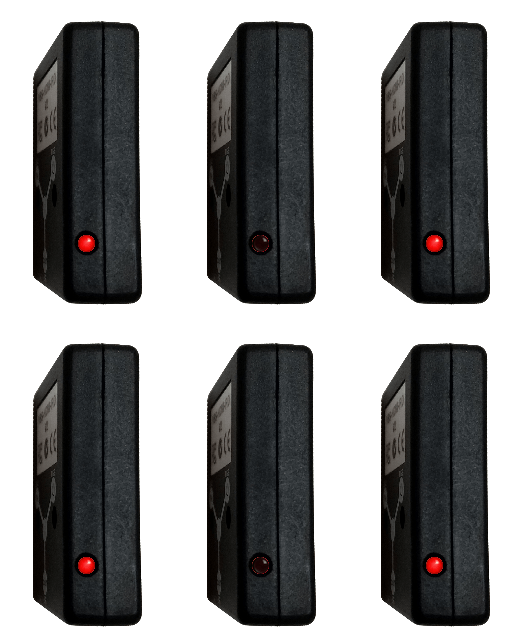 |
| No power. | Powered on. | Receiving a command from the Just Add Power device. |
| Feature | V1 | V2 |
|---|---|---|
| Serial settings | 9600 baud, 8 data bits, no parity, 1 stop bit | 115200 baud, 8 data bits, no parity, 1 stop bit |
| IR formats | Pronto and Global Cache | Pronto, Global Cache, and Global Cache Compressed |
| Status LED | None | Red LED for power and command activity |
Requirements
These instructions are based on the latest firmware available for the applicable device and operating mode. Use L Series firmware for AMP 2G Legacy Mode or B Series firmware for normal Omega Series and Ultra Series operation.
For firmware downloads, see L Series firmware or B Series firmware for Omega and Ultra Series. For L Series hardware limits, see Understand 2G Legacy Mode Compatibility.
For either dongle revision, you also need:
- A network path from the control system to the Just Add Power device connected to the dongle. See How to Access a Device.
- An IR command for the source or display in a format supported by your dongle revision.
Cables and Connections
Both dongle revisions use the same supplied cable set:
- IR emitter (3V, 0.1A).
- 3.5mm-to-3.5mm stereo cable.
- USB Type A to Micro USB cable.
- Y-shaped USB power tap.
Use the connection diagram to identify the dongle's IR, serial, and power connections.

Set the Null Modem Jumper
Locate the null modem jumper on the bottom of the Just Add Power device. It changes the transmit and receive pin positions on the device's RS232 port. Both V1 and V2 dongles require the crossover position.
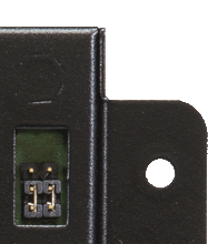
The physical jumper orientation varies by model. For Omega Series and Ultra Series devices, use the model-specific diagrams in Null Modem Jumper Pinouts for Omega & Ultra Series. For 2G Series devices, confirm the crossover position for the exact model before continuing.
Configure the Just Add Power Device
Confirm that the control system can reach the Just Add Power device connected to the dongle. For an established system that requires routing, see Setup a Static Route for an Established Just Add Power System.
Select the firmware section below, then use the command or setting for your dongle revision.
L Series Firmware
CLI
- Open a Telnet connection to the Just Add Power device connected to the dongle on port
23. - Execute the command for your dongle revision:
Dongle Command V1 flux.sh v1V2 flux.sh v2 - Reboot the Just Add Power device.
webUI Alternative for V1
- Open the Just Add Power device webUI.
- Set Serial over IP to Type 3 - CLI Access.
- Set Baudrate to 9600, Data bits to 8, Parity to None, and Stop bits to 1.
- Select Apply.
- Reboot the Just Add Power device.
B Series Firmware
Choose the CLI or webUI method. The Flux setting selects the serial mode and baud rate for your dongle revision.
CLI: justOS API
Execute each command individually. The justOS API is also accessible through HTTP; these instructions use the device CLI.
- Open a Telnet connection to the Just Add Power device connected to the dongle on port
23. - Execute the command for your dongle revision:
Dongle Command V1 POST /settings/flux v1V2 POST /settings/flux v2 - Save the setting:
POST /command/device save. - Reboot the Just Add Power device:
POST /command/device reboot. - After the Just Add Power device restarts, reconnect and execute
GET /settings/flux. Confirm that the configured value matches your dongle:v1orv2.
For API access details and additional startup settings, see justOS API Overview and Startup Settings.
webUI
- Open the Just Add Power device webUI and locate the serial settings under Endpoint Control.
- Select the serial mode for your dongle revision:
Dongle Serial Mode V1 Flux IR Dongle (v1) V2 Flux IR Dongle (v2) - Select Apply.
- Reboot the Just Add Power device.

Send and Verify an IR Command
Use the documentation for your control system to select an IR code in a format supported by your dongle revision. Both methods below support V1 and V2 dongles after the connected Just Add Power device has been configured for the correct revision.
B Series: justOS API through the CLI
- Open a Telnet connection to the IP address of the Just Add Power device connected to the dongle, using port
23. - Execute
POST /command/flux IR_CODE, replacingIR_CODEwith the Pronto or Global Cache command for the source or display. - Confirm that the intended source or display performs the requested action.
Example Global Cache command executed directly in the device CLI:
POST /command/flux sendir,1:1,1,38000,1,1,127,63,16,16,16,48,16,16,16,16,16,16,16,16,16,16,16,16,16,16,16,16,16,16,16,16,16,16,16,48,16,16,16,1000L Series or B Series: Port 4998
- Open a Telnet connection to the IP address of the Just Add Power device connected to the dongle, using port
4998. - Send the IR command followed by a carriage return.
- Confirm that the intended source or display performs the requested action.
Example Global Cache command. Here, \r represents the terminating carriage return.
sendir,1:1,1,38000,1,1,127,63,16,16,16,48,16,16,16,16,16,16,16,16,16,16,16,16,16,16,16,16,16,16,16,16,16,16,16,48,16,16,16,1000\rConfirm the result at the source or display. Feedback from the Just Add Power device and LED activity on a V2 dongle do not confirm that the controlled source or display performed the requested action.
Command Feedback
For both V1 and V2, the Just Add Power device acts as the gatekeeper: it checks command structure before forwarding the command to the dongle and provides feedback to the control system. Feedback is not returned by the dongle.
| Command | Documented Response |
|---|---|
| Global Cache IR code | completeir,1:1,1 |
| Incorrect Global Cache code | ERR_001 |
| Pronto IR code | ERR_001 |
getdevices |
device,0,0 ETHERNET |
getversion |
V2 example: version,1,FluxCapacitor_v2 |
get_NET |
NET,0:1,[configlock],[ipsetting],[ipaddress],[subnet],[gateway] |
get_IR |
IR,1:1,IR |

